A console application called "BladeBatch.exe" is included with the BladeGen installation. This program will read either a Batch Input File (’bgi’ extension) or a BladeGen file (’bgd’ extension) in conjunction with command line parameters describing changes to the geometry (’bgi’ input file only) and the output files. It will then apply the changes and output the new geometry in one of the formats shown in the table below.
Table 9.13: Output Formats Supported by the BladeBatch Program
|
File Extension |
Description |
|---|---|
|
’bgd’ |
BladeGen Data File |
|
’bgi’ | |
|
’rtf’ |
BladeGen Report (Rich Text Format) |
|
’bgr’ | |
|
’ibl’ | |
|
’dxf’ | |
|
’igs’ | |
|
’tin’ |
ICEM TETIN File |
|
’curve’ |
Note that the file extension specified on the command line determines the output format. Geometry changes may also be applied by modifying parameters or specifying equations within the input ‘bgi’ file. This powerful capability allows users to perform design sensitivity studies and optimizations. For details on the syntax for the ’bgi’ file format see the topic Batch File Format (BGI).
The following topics are discussed:
The following command syntax description is available by executing BladeBatch without any parameters. This output will be kept up to date and therefore is the best description of the files and options supported.
Command Syntax: (output when BladeBatch is executed without any parameters)
CFX-BladeBatch v4.1.033 Sep  7 2006

Fatal Error: Too few arguments specified.

   syntax:   BladeBatch {InputFile} [-Dvar=val] [OutputFile1] [OutputFile2]...

   where:
      {InputFile}     bgd or bgi file.

      [OutputFile#]   bgd, bgi, bgg, bgp,
                      rtf, bgr, rtzt,
                      txt, ibl, dxf, igs, or tin.

      [-D[ ]var=val]  Represents one or more optional variable definitions.
                      Overrides default variables for bgi input files.

                      Enclose the variable, equal sign, and equation in quotes
                      if spaces are added.

      [-TG[ ][path]]  Creates CFX-TurboGrid Files in the current or specified
                      path.

      [-2D[ ][path]]  Creates 2D DXF Files in the current or specified path.

   Example:
      BladeBatch test.bgi -DNumBladeSets=12 results.bgd -IP- results.igs

   Report Files require two file names, in the proper order:
      BladeBatch test.bgd Report.rtf Template.bgr

   IGES files have optional parameters specified before the filename:
         [-I:B+C+S+2+3-E-X=0.0U=1F=1.0] (default options)
            B         Export B-Spline (instead of Piecewise-Linear) curves.
            C         Include Blade Curves
            S         Include Blade Surfaces
            2         Include Hub & Shroud 2D Curves
            3         Include Periodic Surfaces
            T         Trim Hub/Shroud Surfaces (if 3)
            E         Use Blade Extenson Curves (if defined)

            X=x.xxx   Extend through Hub/Shroud
            U=x       IGES Units Designator
                         (1=IN,2=MM,4=FT,5=MI,6=M,7=KM,
                          8=MIL,9=UM,10=CM,11=UIN)
            F=x.xxx   Scale Factor

   2D DXF files have optional parameters:
         [-2D:MV+IV+OV+BV+MT+BT+DS+DO+DC+] (default options)
            MV        Export Meridional View
            IV        Export Inlet (Z+) View
            OV        Export Outlet (Z-) View

            BV        Export Blade View
            MT        Export Meridional Table
            BT        Export Blade Table
               Table Options:
               DS        Data Set, 0=Meanline, 1=Side1, 2=Side2, 3=Both
               DO        Data Oriented Normal to Mean (false is tangential)
               DC        Data Coordinates Cylindrical (false is Cartesian)

      BladeBatch test.bgd -IP+C+S+2+3-E-X=0.0U=1F=1.0 test.igs
The power of the batch processing is in the ’bgi’ file. This file allows the user to specify equations for key parameters so that the blade geometry can be modified, from the command line, to generate a range of geometry for CFD evaluation. The following discusses the process of setting up and running a batch file.
The main concept with ’bgi’ files is that variables must be accessed indirectly from the command line. For example, to set the number of blades, perform the following steps. These steps are detailed in the Step by Step Example.
Create an "example.bgi" file from BladeGen (See Creating a BGI File).
Edit the "example.bgi" file using the BGI File Editor Dialog (See Editing a BGI File).
Create a NumBladeSet variable with a default value in the "Defaults" section.
Begin Defaults
      NumBladeSets = 11
   End Defaults
Modify the "Model" section to use the parameter.
Begin Model
      NumMainBlade = NumBladeSets
      :
      :
   End Model
Execute BladeBatch with the new blade count on the command line (See Running a BGI File). BladeBatch example.bgi -DNumBladeSets=11 example.bgd
This same process can be used to assign values to points and other variables.
The following topics are discussed:
A ’bgi’ file can be created by hand, BladeGen, or an external program. In this example, the file will be written by BladeGen, using the following steps.
Execute BladeGen and create a new "Radial Impeller" using the defaults for geometry and layers (2 Angle, 1 Thickness, and 5 Output Layers) by selecting the File | New | BladeGen Model menu command and pressing OK in the dialogs that are displayed.
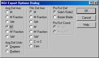
Use the File | Export | Batch Input File... menu command to export the ’bgi’ file. Specify "d:\example.bgi" for the filename in the Save As dialog box and press Save. Use the default settings in the BGI Export Options Dialog (shown below) by pressing OK.
The BGI File Window will now be displayed. Go to Batch Processing - Editing a BGI File for the next steps.
This topic is a continuation of the Creating a BGI File topic.
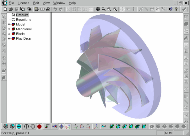
When the file is saved, the BGI File Window will be displayed. See the figure below (The blade geometry may not appear as shown.). This window can also be accessed by using the File | Open... menu command and specifying a ’bgi’ file.
Once the window is displayed, perform the following steps to edit the file.
Right mouse click on the Defaults section and select the Edit Equation Set menu command.
Type "NumBladeSets=11" in the dialog and press the OK button.
Right mouse click on the Model | Num Main Blades variable and select the Edit Value menu command.
Enter NumBladeSets in the dialog and press the OK button.
Save the bgi file by using the File | Save menu command.
Go to Batch Processing - Running a BGI File for the next steps.
This topic is a continuation of Batch Processing - Editing a BGI File.
The following steps are used to execute BladeBatch with parameters on the command line and export a new ’bgd’ file. The first step is required if the BladeGen is not already on your path and assumes the default installation path (replace with the actual path if different).
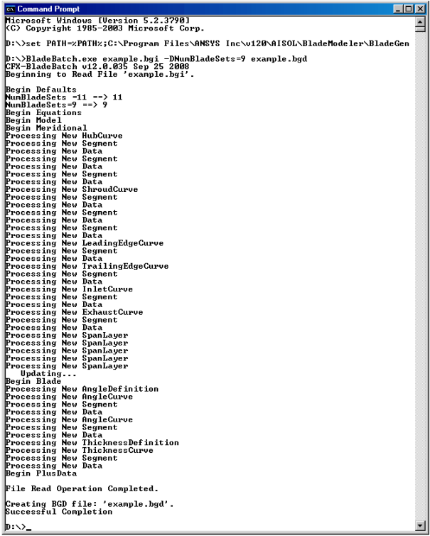
At the command line type the following commands.
set path=%path%;c:\Program Files\ANSYS Inc\v110\AISOL\BladeModeler\BladeGenBladeBatch example.bgi -DNumBladeSets=9 example.bgd
The results are shown in the figure below.