Defining Boundary Layers After Meshing
- On the ribbon, click Layers
 .
. -
Click Select face
 and pick the
blocking face(s) that you want to offset. Press the Ctrl key or use the selection
filter to determine selection preference.
Alternatively, click Select body
and pick the
blocking face(s) that you want to offset. Press the Ctrl key or use the selection
filter to determine selection preference.
Alternatively, click Select body and pick the
entire blocking body. Then, click Select target face
and pick the
entire blocking body. Then, click Select target face  and
pick the block faces that you do not want to offset. This selection process may be
simpler for more complex geometries.If you are selecting faces for a fluid flow simulation, you typically want to pick faces that represent a wall boundary. For a structural simulation, you typically want to pick faces that represent a boundary where you anticipate high stress, and you want your mesh to have anisotropy so that you can capture the stress gradient near the boundary.Tip: For complex models in which multiple faces require boundary layers, or to select internal block faces, you may find the Inverse Selection option from the context sensitive (RMB) menu helpful.For surface bodies, the selection processes are similar except you will select block edges instead of faces to offset. If layer modification is required, click Select block edge
and
pick the block faces that you do not want to offset. This selection process may be
simpler for more complex geometries.If you are selecting faces for a fluid flow simulation, you typically want to pick faces that represent a wall boundary. For a structural simulation, you typically want to pick faces that represent a boundary where you anticipate high stress, and you want your mesh to have anisotropy so that you can capture the stress gradient near the boundary.Tip: For complex models in which multiple faces require boundary layers, or to select internal block faces, you may find the Inverse Selection option from the context sensitive (RMB) menu helpful.For surface bodies, the selection processes are similar except you will select block edges instead of faces to offset. If layer modification is required, click Select block edge and
pick the internal block edge(s) as shown in the example.
and
pick the internal block edge(s) as shown in the example.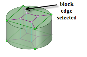
- Click Complete
 to create
the boundary layer control.
to create
the boundary layer control.
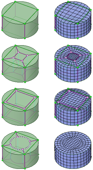
The following sequence of images shows the blocking structure for various options on a simple cylinder with disabled and enabled mesh display.
- The top row shows the basic blocking with no layers. Cells near the vertices on the curved surface are highly skewed.
- The second row shows the how the blocking is split to accommodate the layers using a Relative offset value of 1.0. Note that boundary layers were created only on the cylinder side faces.
- In the third row, the split was modified by setting the relative offset value to 0.2.
- In the bottom row, the layer control was created with Link shape enabled and an offset value of 0.75. (Block cage display is disabled.)