


This multi-part tutorial shows how to create an advanced oSP3D analysis, combining multiple field-MOPs and a custom algorithm. The oSP3D analysis is then exported as an FMU, allowing consumption with Ansys optiSLang or Ansys Twin Builder, which is part of Electronics Desktop.
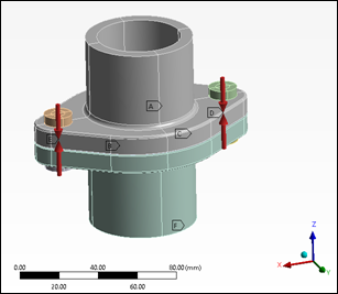
The objective of this analysis is to determine if the gasket is tight, given a certain bolt pretension and pressure of the flowing medium.
For background information, see Gasket Tightness in the optiSLang 3D Post-Processing User's Guide.
To learn how to create a design of experiments from an Ansys Mechanical project using optiSLang, see Exporting Field Data from Ansys Mechanical for Use in oSP3D and optiSLang.
The folder oSP3D_examples\ansys\gasket
contains the files that are used in this tutorial. Because the oSP3D database file
gasket_tightness.sdb already contains imported simulation data
and field-MOPs, if you load this file, you can skip to Exporting the Custom Analysis Workflow as an FMU.
However, if you want to step through the entire process in a new oSP3D database file,
perform the procedures in the next two topics.
To identify the contact tightness algorithm.
Select > > .
In the Manage macros window, select the macro identifyContactTightness and click .
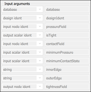
In the Edit chunks / macros window, the Input arguments area displays two scalar parameters that tune the algorithm (minimumPressure and minimumContactState) and two variables of type string that set the named selections of the inner and outer closed rings across which tightness is to be evaluated.
After viewing these arguments, close the Edit chunks / macros window and then the Manage macros window.
In a new oSP3D project, import the simulation data:
To import the reference mesh, select > > and open sos_mesh.cdb in
oSP3D_examples\ansys\gasket\workflow\gasket.opd\Sensitivity\Design0002\dp0\SYS-6\MECH\SoS_Export.Note: Design0001 failed and no mesh was exported during the DOE.
To import named selections for the inner and outer edges:
Select > > and open ns_gasket_seal_edge_inner.csv in
oSP3D_examples\ansys\gasket\components.Set the identifier to INNER_EDGE and create a node set.
Select > > and open ns_gasket_seal_edge_outer.csv in
oSP3D_examples\ansys\gasket\components.Set the identifier to OUTER_EDGE and create a node set.
Caution: The identifiers for the named selections must be set precisely to INNER_EDGE and OUTER_EDGE. Otherwise, the identifyContactTightness algorithm fails.
To import field designs:
Select > > .
In the Files to parse area, add the LS-PrePost output file sos_results.k in Design0002\dp0\SYS-6\MECH\SoS_Export.
Set Path of reference design to \
oSP3D_examples\ansys\gasket\workflow\gasket.opd\Sensitivity\Design0002\.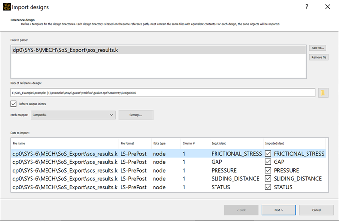
Finish the import.
The number of field designs imported should be 45.
To import scalar input parameters:
Select > > and open StartSet.bin in
oSP3D_examples\ansys\gasket\workflow\gasket.opd.Accept the default values in the Import scalar parameters to oSP3D window.
Select > .
Note: During the DOE, some designs have failed to produce results. Designs without field results must be excluded from field-MOP training.
To create field-MOPs:
Select > > .
Drag and drop all scalar quantities to the Input (selectable) list.
Drag and drop the field node quantities STATUS and PRESSURE to the Output list.
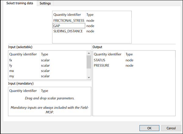
Click to create the field-MOPs with the default settings.
By evaluating the two newly created field-MOPs, you are now ready to approximate the contact pressure field and contact state field for any given set of input parameters (within the range of training data).
To determine if the gasket is tight for a given set of input parameters, you can export the macro-based custom analysis workflow as an FMU.
Note: If you skipped to this step after loading the oSP3D database file gasket_tightness.sdb, you can export the custom analysis workflow in this database file as an FMU.
To export the custom analysis workflow as an FMU:
Select > > .
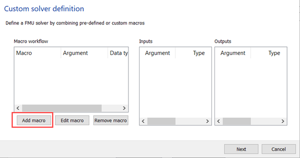
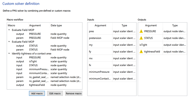
In the Custom solver definition window, click .
Select Evaluate Field-MOP
nodeEvaluateFieldMOP.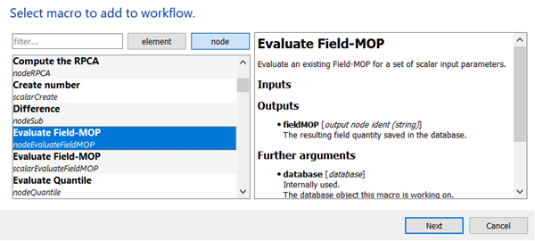
Click .
In the fieldMOP field, enter
PRESSURE.From the fmopIdent list, select .
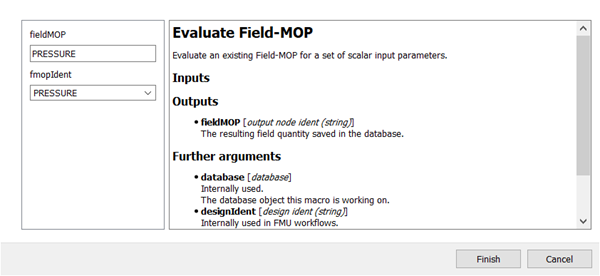
Click .
The macro is added to the custom solver definition.
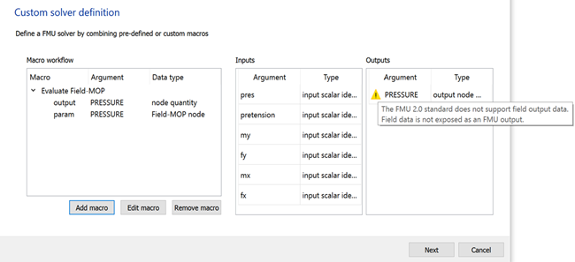
Click .
Select Evaluate Field-MOP
nodeEvaluateFieldMOP.In the fieldMOP field, enter
STATUS.From the fmopIdent list, select .
Click .
The macro is added to the custom solver definition.
Click .
Select Identify tightness of a contact area.
Enter the following information:
Field Value pressureField PRESSURE isTight isTight contactField STATUS minimumPressure minimumPressure minimumContactState minimumContactState Named selection ns_gasket_seal_edge_inner Named selection ns_gasket_seal_edge_outer tighnessField tightnessField 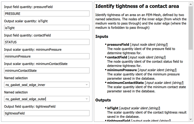
Click .
The macro is added to the custom solver definition.
Add additional macros of your choice.
For example, you might add the macro for extracting the maximum value of the PRESSURE field.
Click .
Click the folder icon.
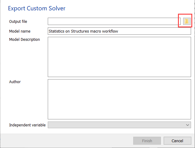
Select a file name, type, and location for your exported FMU file.
Click .
The file path is added to the Output file field.
Click .
In a tool of your choice, execute the exported FMU. The following tools are recommended:
Ansys optiSLang (FMU_oSL3D custom integration node)
Ansys Twin Builder
FMPy in a Python environment