


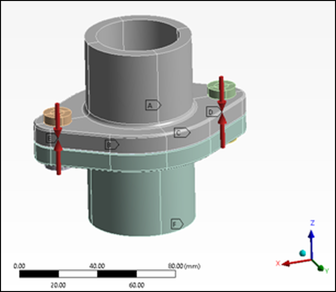
The folder examples\ansys\gasket
contains an example for evaluating whether a gasket is tight given a certain bolt
pretension and pressure of the flowing medium.
The oSP3D analysis is based on simulation data from Ansys Mechanical. It demonstrates how multiple field-MOPs and custom algorithms can be combined in a single oSP3D analysis to return a meaningful scalar output.
The ultimate goal is to quickly determine the gasket’s tightness when given new input parameters, without running a computationally expensive simulation. The oSP3D analysis consists of the evaluation of two field-MOPs and a sophisticated algorithm for assessing whether the flowing medium remains contained.
The oSP3D analysis is then exported to an FMU 2.0 file. This file takes the scalar input parameter and determines whether the gasket remains tight. The exported FMU2.0 file can then be consumed in supporting tools, such as Ansys optiSLang and Ansys Twin Builder.
The following image shows the three steps in the oSP3D analysis. The inputs and outputs that enter and leave the frame are scalar values exposed by the FMU 2.0 file.
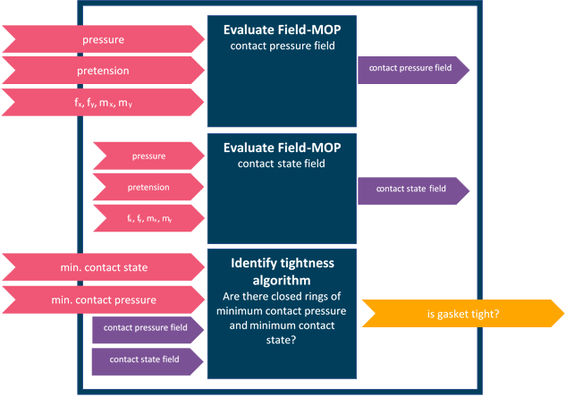
The flowing medium’s pressure acts against the contact pressure field between the lower and upper gasket part. The medium can escape only if it finds a continuous path where either or both of these conditions are met:
The two gasket parts are not in close contact.
The contact pressure field’s magnitude is below a certain threshold.
The contact pressure field forms a closed ring with a magnitude of at least 6 MPa. The flowing medium cannot escape, if additionally, the upper and lower gasket parts form a similar closed ring of close contact.
Thus, to calculate the desired Boolean output variable (whether the gasket is tight), two fields must be considered:
Contact state field (close contact/open contact)
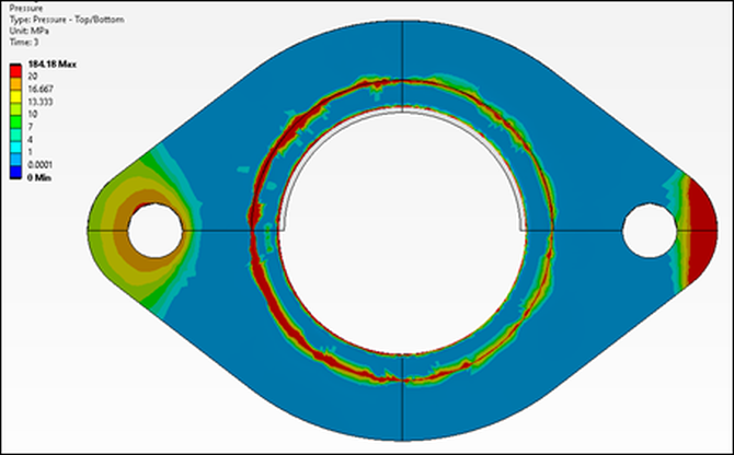
Contact pressure field
Ansys Mechanical is used to simulate these two fields for a given set of input parameters.
First, Ansys optiSLang runs a design of experiments (DOE), varying the input parameters and exporting the simulated field data. This image shows the DOE workflow in optiSLang.
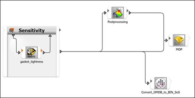
Subsequently, in oSP3D, field-MOPs are created for both fields.