


This example uses Named Selections to assign material properties in the DesignLife Add-on.
| Analysis Type | Fatigue |
| Features Demonstrated | DesignLife Add-on, DesignLife system |
| Licenses Required | Ansys Mechanical Enterprise PrepPost and Ansys nCode Premium/Enterprise |
| Help Resources | DesignLife Add-on |
| Tutorial Files | FatigueNamedSelection.zip |
This tutorial guides you through the following topics:
The data file for this tutorial can be found here on the Ansys customer site.
The file you need is:
sae_shaft_1.wbpz - this is the model that you will set up by following the steps below. Copy the file to a working folder and complete the worked example using the copy. Make sure that you have write permission to the working folder.
Start Workbench and select > .
Browse to your working directory and select sae_shaft_1.wbpz.
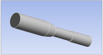
The model is a steel shaft subjected to a constant bending load. The shaft was manufactured by a rolling process, and the center section was then machined down to final tolerances.
The first step is to define the material properties to be used in the analysis:
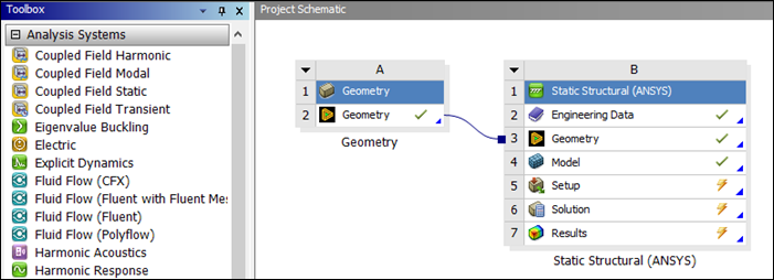
Right-click the Engineering Data cell (B2) and select .
Click the Engineering Data Sources tab located at the top of the form to expose the Engineering Data Sources window.
This window lists the data sources available.
Scroll down and select
nCode_matml.If
nCode_matmlis not a currently-available data source, scroll to the bottom of the list and select (see below). Then browse to the GlyphWorks/mats folder in your ANSYS nCode DesignLife installation and select nCode_matml.xml.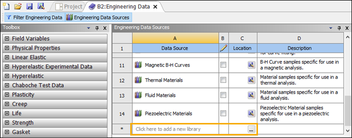
Once
nCode_matmlis selected as a Data Source, its contents will be visible in the Outline of nCode_matml panel. Scroll down in that panel to find the AISI_4340_125 dataset. Click the button (see below) for that dataset to add it to the Contents of Engineering Data.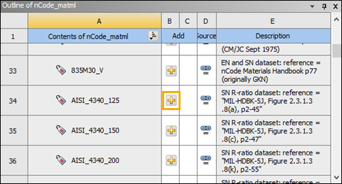
Click the Engineering Data Sources tab again to hide the Engineering Data Sources panel and verify that AISI_4340_125 has been added to the Contents of Engineering Data (below).
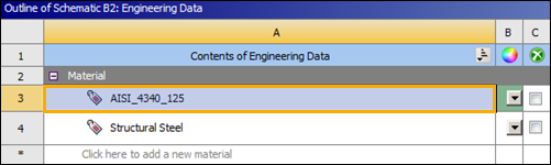
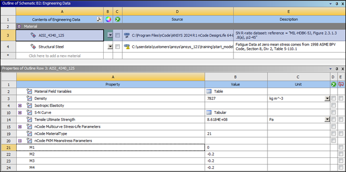
Select AISI_4340_125 in the Outline of Schematic B2: Engineering Data (above) to display its properties in the Properties panel.
The selected material contains the appropriate ANSYS and nCode material definitions for performing a stress life analysis in DesignLife using a multicurve interpolation mean stress correction. You will add an additional property set to this material to allow it to be used to perform an FKM mean stress correction.
Under nCode Properties in the Toolbox, select nCode FKM Meanstress Parameters and drag it onto AISI_4340_125 in the Contents of Engineering Data column.
In the Properties panel for AISI_4340_125, set the nCode FKM Meanstress Parameters to the following values:
M1 =
0.0M2 =
−0.2M3 =
−0.2M4 =
−0.2
Click the Project tab to return to the Project.
Right-click the Model cell (B4) and select .
Select if requested to read the upstream data.
This opens the model in Mechanical.
Expand the Geometry element in the project tree and select Solid.
In the Details panel, under Material, set the Assignment to
AISI_4340_125.From the Home toolbar, select .
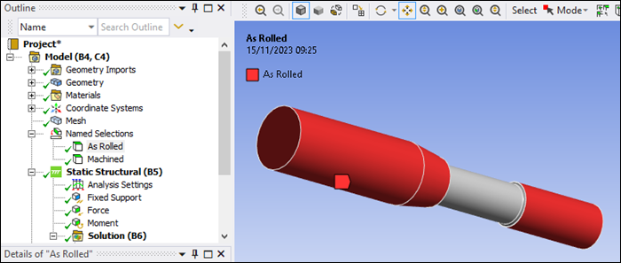
Expand the Named Selections element under Model (B4) in the project tree.
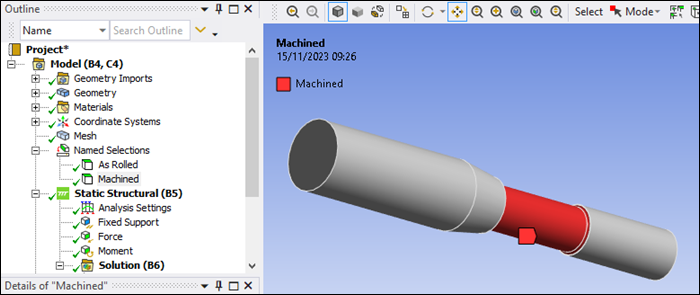
Select As Rolled and then Machined and observe the pre-defined Named Selection scopings as shown in the figures below. These define portions of the model that will be assigned different surface finish corrections.
Named Selection As Rolled:
Named Selection Machined:
To make the DesignLife capabilities available, click the icon in the ribbon.
The icon is highlighted in blue, indicating that the add-on is loaded.
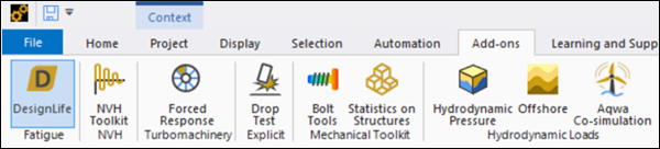
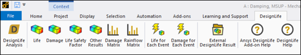
Once the add-on is loaded, the Ansys nCode DesignLife ribbon is visible, exposing all the DesignLife capabilities.
From the DesignLife ribbon, select to insert a new DesignLife analysis directly from Mechanical.
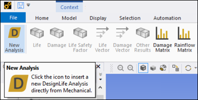
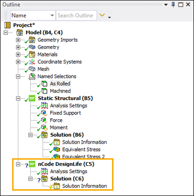
Click the New Analysis icon and verify that the nCode DesignLife (C5) object is inserted into Mechanical.
In Workbench, verify that a Mechanical Embedded DesignLife system has been added to the project.
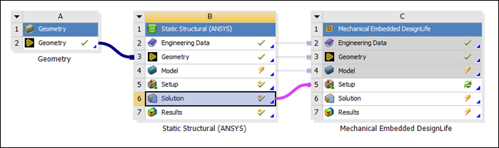
Select the Solution cell of the Static Structural system and connect it to the Setup cell of the Mechanical Embedded DesignLife system.
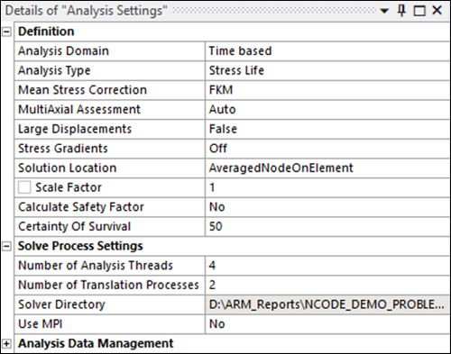
In Mechanical, select the Analysis Settings element under nCode DesignLife (C5) in the project tree.
Set the Analysis Type to .
Set the Mean Stress Correction to .
Under Solve Process Settings ensure that the following options are set correctly:
Set the Number of Analysis Threads to
4(default).The Number of Analysis Threads property can be used to set the number of threads for a job or an individual run. For a distributed job, this count will apply to each process that comprises the job. This property corresponds to the NumAnalysisThreads parameter in the input.dcl file consumed by the nCode solver. More than four threads requires an Ansys nCode DesignLife Parallel Add-on license.
Set the Number of Translational Processes to 2 (default).
This property controls the number of processes used simultaneously during the translation process. It corresponds to the NumTranslationProcesses parameter in the input.dcl file consumed by the nCode solver.
Select the Solution Group element in the project tree and check the settings.
This defines the portion of the geometry that will be used for the fatigue analysis calculation. By default, all bodies are selected. In this case, there is only one geometry, so there is no need to modify the setting.
You will now add a Loading Event for the system and set the loading condition to the first time step of the structural analysis.
Select the Load Mapper element in the project tree.
Click the button next to Add Loading Event and click .
This adds the first Loading Event.
Select the newly-created Loading Event and check that the loading Type is set to .
Set Repeat Count to
1e9.The fatigue loads can be either Constant Amplitude, Time Step or Time Series for the Time based domain.
Under Add Load, click and then to create a new .
Ensure that Environment is set to and set Define By to .
Set the Time to
1.This sets the loading condition to the first time step of the structural analysis.
Set the Max Factor to
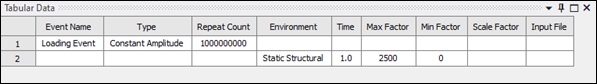
2500and Min Factor to0.Re-select the Loading Event object in the project tree.
The details of the Loading Event are visible in the Tabular Data view.
You will now add a Materials Assignment object to modify the material used in the fatigue calculation. Be aware that the upstream systems connected to nCode will still use the material defined in Engineering Data. Only the material parameters for the fatigue calculation within the nCode system will be modified.
For more information, see Materials Assignment in the Mechanical Add-ons Guide.
Right-click Materials under the nCode DesignLife (C5) tree element and select Modify Material Parameters.
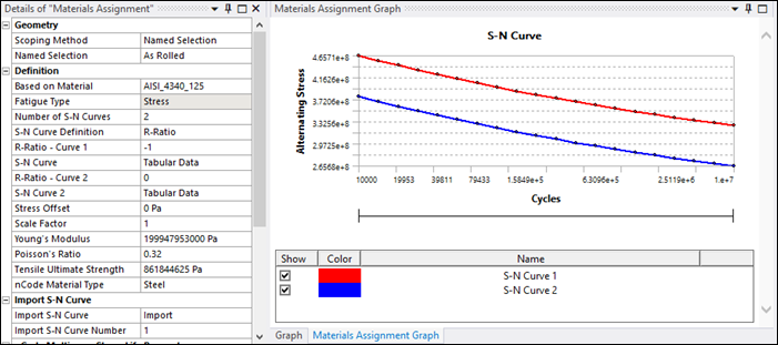
Set the Scoping Method to and select the named selection.
The Based on Material property will be set to
AISI_4340_125by default, with properties as defined in the engineering data.In the Details panel, under Definition, set the nCode Material Type to .
Under Material Parameters, set the Surface Finish to .
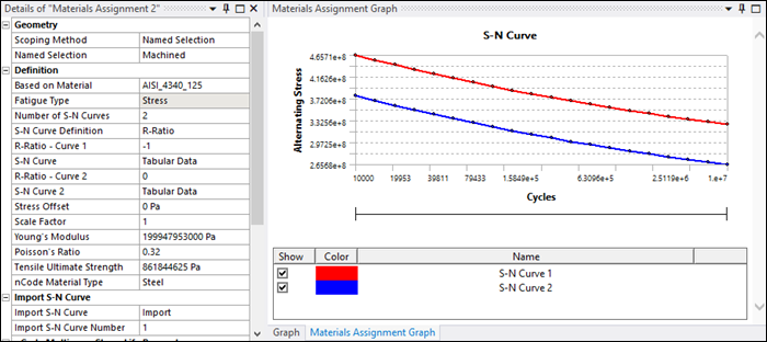
The S-N Curves are displayed in Mechanical in the Materials Assignment Graph panel.
Right-click Materials under the nCode DesignLife (C5) tree element and once again select Modify Material Parameters.
This creates a new Materials Assignment 2 object.
Set the Scoping Method to and select the named selection.
In the Details panel, under Definition, set the nCode Material Type to .
Under Material Parameters, set the Surface Finish to .
The S-N Curves are displayed in Mechanical in the Materials Assignment Graph panel.
Right-click the Solution (C6) object in the project tree and select .
While solving, selecting Solution Information will show the solver's progress and display errors as they are encountered.
The fatigue results may be viewed as either life or damage.
Insert and results by clicking those buttons in the DesignLife toolbar with Solution (C6) active in the tree.
Alternatively, right-click the Solution (C6) object and insert Life and Damage results (see below).
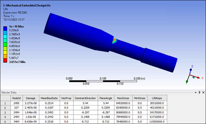
Observe that the Tabular Data contains the 5 most damaged nodes.
If a NodeId is selected in the table, this node will be highlighted in the graphics window.
Change the Most Damaged Ids to Display property to
15.This filters the number of node Ids to display in the tabular data. Observe that the tabular data immediately updates.
Select the first 4 most damaged nodes from the tabular data NodeId column to highlight these in the graphical display (see below).
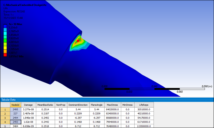
You have completed the fatigue analysis using Named Selections and accomplished the overall objective for this tutorial.
Congratulations! You have completed the tutorial.