


Include a Materials Assignment object to modify the material used in the fatigue calculation. Be aware that the upstream systems connected to nCode will still use the material defined in Engineering Data. Only the material parameters for the fatigue calculation within nCode system will be modified.
Note: When using the DesignLife add-on, Young's Modulus and Tensile Ultimate Strength properties must be defined for all materials in the engineering data. No comma symbols are allowed in the material name.
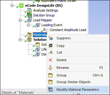
Right-click Materials and choose .
Scope the part that you would like to analyze with a different material. If elements have more than one Materials Assignment applied to them, the first Material Assignment defined in the tree will be used.
The Materials Assignment properties can be defined from a material used in the analysis, defined within Engineering Data () or picked from an nCode material *.mxd database ().
Manual Material Properties Definition
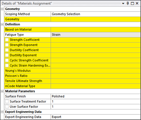
Pick a Based on Material from engineering data to base the new material on an existing material's data.
For a Fatigue Type analysis, set the Strength Coefficient, Strength Exponent, Ductility Coefficient, Ductility Exponent, Cyclic Strength Coefficient, Cyclic Strain Hardening Exponent, Young's Modulus, Poissons's Ratio, and Tensile Ultimate Strength of the new material.
When the material properties are fully defined, the Strain-Life relationship is represented. Shown below is the Coffin-Manson-Basquin formula, defining the relationship between strain amplitude
 and the number of cycles to failure
  :
:
The elastic life is given by:

where
 is the strength coefficient, E is the Young's
Modulus and b is the strength exponent.
is the strength coefficient, E is the Young's
Modulus and b is the strength exponent.The plastic life is given by:

where
 is the ductility coefficient and c is the
ductility exponent.
is the ductility coefficient and c is the
ductility exponent.The total life is given by the sum of the elastic and plastic life:

Graphically, this is displayed as shown below:
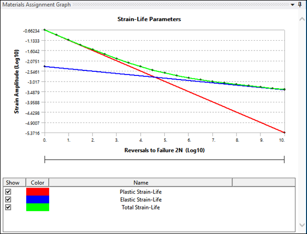
Fatigue damage is predicted in the same way as for the S-N method - the damage due to an individual cycle is calculated by looking up the strain amplitude of that cycle on the curve to find the number of reversals to failure 2Nf. The damage assigned to that cycle is then 1/Nf.
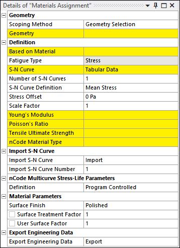
For a Fatigue Type analysis, set the S-N Curve, Stress Offset, Scale Factor, Young's Modulus, Poissons's Ratio, and Tensile Ultimate Strength of the new material.
For Stress Analysis, the nCode Multicurve Stress-Life Parameters are set to and populated from engineering data (if defined) when the Materials Assignment is created.
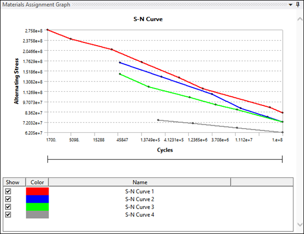
To import an S-N Curve, select a *.csv file containing the cycles data in the first column and the alternating stress in the second column. Multiple curves must be imported separately.
If nCode Multicurve Stress-Life Parameters are not defined in the engineering data, the definition is set to and default values for
Nfc,SEIs, andNeare used (see below).Parameter Description Default Value Nfc Numerical fatigue cutoff life, in cycles. Beyond this life, damage will be assumed to be zero. 1e+30 SEIs Standard error of log10(stress). 0.054018 Ne Endurance limit. This is the specified life in cycles. The main function of this is to define the point on the S-N curves where surface finish corrections are applied. 1e+7 Each defined S-N curve is displayed as shown below:
Set the nCode Material Type to one of , , , , , , and .
Note: When calculating Stress Life or Safety Factor analysis, the material definition should be consistent for all the materials used in the model. If a material uses SN Curve-defined , care should be taken to ensure that for all materials assigned in the analysis, SN Curves are defined using Mean Stress and likewise for R-Ratio (see Fatigue Material Properties for more information).
Materials Database Definition
As an alternative to the manual method above, material properties can be selected from an nCode material database.
The default materials applied for the analysis are taken from the
iceflow_standard.mxddatabase, which can be found in thematsfolder in the nCode installation. If the Analysis Type is or , the default material isseam_steel. If the Analysis Type is , the default material isValox 508 GF30.To modify the default material for , , , , , or analysis:
Insert a Materials Assignment object.
In the case of analysis, the S-N Curve Definition property must first be defined as either , , or .
In the case of analysis, the S-N Curve Definition property must first be defined as either or .
Set the Database by selecting the
*.mxddatabase file where all the nCode materials are defined.This file is copied to the current directory. The DesignLife add-on filters the materials found in this database.
For and , it lists those that are valid for analysis (
nCodeSNMeanStressCurveContainerornCodeSNRRatioCurveContainertype).For , it lists those that are valid for analysis (
nCodeENMatDatatype).For and , it lists those that are valid for analysis (
nCodeSNSeamWeldMatDatatype).For , it lists those that are valid for analysis (
nCodeSFCBasquinCurveContainertype).For or , if is selected, it lists those that are valid for temperature-dependent analysis (
nCodeSNTemperatureCurveContainerornCodeENTemperatureCurveContainertypes). In this case, the Default Temperature parameter for the material will also be exposed and assigned to the scoped material assignment parts.Select the new Material.
Note: If the database material selected is a mean stress curve that does not contain mean stress curve defined at zero, you will get an nCode solver error stating that the Multi curve material contains no curve with mean stress. To avoid this, ensure the Mean Stress Correction in the analysis settings is set to .
Surface Finish and Surface Treatment Settings
Surface finish and treatment can have a significant effect on fatigue behavior. Rough surface finishes due to machining marks, for example, will in general reduce the fatigue strength, whereas surface treatments are often applied to increase the fatigue strength.
In , surface finish and treatment effects are modeled in the S-N and E-N engines by means of a single surface factor Ksur. This works in a different way from the scale factor described above, with which it should not be confused. The surface factor is used to adjust the material curve. The application is slightly different for the S-N and E-N methods, but the basic principle is the same—the surface factor is applied to the fatigue strength of the material in the high cycle (long-life) regime, but the effect reduces in the low cycle (short-life) regime. The details of the application of the surface factor are given in the , with the sections describing the S-N and E-N analysis engines. Ksur is the product of three factors, which can be defined via the material map. Each of these has default value of 1.
Ksur = Ktreatment x Kuser x Kroughness
Where Ktreatment is the Surface Treatment Factor, Kuser is the User Surface Factor and Kroughness is the Roughness factor.
Set the Surface Treatment Factor to adjust the fatigue strength to take into account surface treatment. A factor > 1 will result in an improvement in fatigue strength. The Surface Treatment Factor should be a positive float number. The default value is 1.0.
Set the User Surface Factor to adjust the fatigue strength for any unspecified reason. A factor > 1 will result in an improvement in fatigue strength. The User Surface Factor should be a positive float number. The default value is 1.0.
The Roughness factor is defined through the Surface Finish property.
If one of the surface roughness descriptions is selected (, , , , , or ), the value for the surface roughness is as shown in the table below.
Condition Rz(μm) Polished 0 Ground 12.5 Machined 100 Poor Machined 200 As Rolled 200 As Cast 200 If the Surface Finish is set to , the Surface Roughness [microm] setting is exposed. The Surface Roughness Factor will then be calculated based on the specified value.
If the Surface Finish is set to , the Roughness Factor setting is exposed to be set directly, based on your experience or on experimental evidence.
Materials Assignment for Gray Iron Analysis
For a type analysis, set the nCode Gray Cast Iron Parameters. These parameters are automatically populated from engineering data. If the selected base material does not contain the Gray Iron material properties, they must be defined manually (see table below).
The Gray Iron dataset consists of the following properties:
| nCode Parameter Name | Description |
|---|---|
| UTS | Ultimate Tensile Strength. This is required to apply the static failure criterion. |
| E0 | Tangent modulus at zero |
| nt | Tensile strain hardening exponent |
| Kt | Tensile strain hardening coefficient |
| Nc | Compressive strain hardening exponent |
| Kc | Compressive strain hardening coefficient |
| mc | Compressive secant slope |
| mu | Unloading secant slope |
| Ks | Damage curve co-efficient |
| ns | Damage curve exponent |
| RC | Damage curve cutoff |
| SD | Standard error of log life |
| mt | Tensile secant slope |