


Aerocoupling on Cyclically Symmetric Structures
Aerodynamic coupling effects can be included in the Forced Response analysis. Aerodynamic coefficients account for vibration-induced pressure fluctuations on the blade surface, and contribute to the stiffness and damping of the system. These values can be computed according to the equations for Aerodynamic Coupling in the Mechanical APDL Theory Reference and are included in the cyclic mode-superposition harmonic response using the CYCFREQ,AERO command. The aerodynamic coefficients can be computed directly using a CFD flutter or aero damping analysis. The aerodynamic coupling coefficients can also be computed using CFD pressures in conjunction with the AEROCOEFF command. For more details on computing and including aerodynamic coefficients, see Aero Coupling.
Aerocoupling Load Definition
The aerocoupling or aerodamping can be included if the coupling files have been generated using cfx.
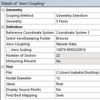
The Reference Coordinate System of the AeroCoupling objects must be selected so that the Source Points are aligned with the Geometry. You can check if they are aligned by switching the Display Source Points to . If the Source Points are displayed correctly, that means the Coordinate System definition is correct.
Select the faces on which the pressure is applied. By default the same faces and coordinates as the ones selected for Force Response Pressure Map will be selected. You might also use the Seek function after selecting the files.
Browse for a folder containing all the aerodamping files, or enter each file using the Tabular Data tool
Check to make sure that the nodal diameters are associated with the correct file. To better understand the concept of nodal diameter refer to Modal Cyclic Symmetry Analysis.
The aero scaling and nodal diameter will be read from the files and may be modified.
If no mistuning is present (or if mistuning is suppressed), the blade, blade interface, and number of cantilever mode shapes must be defined. If mistuning is created afterwards or unsuppressed, select the aerocoupling object in the tree again to remove the selection.
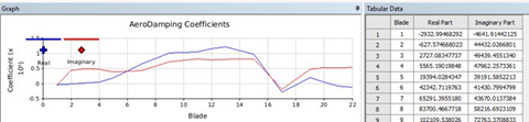
Right-click the AeroCoupling object, and choose to generate the aerodamping coefficients.
The aerodamping coefficients for each blade will be displayed.
If you press Solve before generating the aerodamping, the coefficient will be calculated before solving.
Understanding Changes to ds.dat
The blade elements and interferences nodes are defined according to the scoped geometry or the defined mistuning object.
/COM AEROCOEFF command computes the aero-damping and stiffness coefficients, and writes them to an APDL array.
PARRES,CHANGE,AeroParm,PARM
*STAT,FileAeroArray
CYCFREQ,AERO,FileAeroArray specifies the array containing the aerodynamic damping coefficients.