When comparing the add-on results in the frequency domain to standalone DesignLife results, the settings for the standalone DesignLife Vibration Generator Glyph must be compatible. This section describes how to ensure that compatibility for each vibration loading type.
- 1.3.5.3.1. Single Frequency Loads
- 1.3.5.3.2. Frequency Range Loads
- 1.3.5.3.3. Consistent Acceleration Loading
- 1.3.5.3.4. Vibration Generator Properties
- 1.3.5.3.5. Vibration Load Provider
- 1.3.5.3.6. DesignLife SineDwell Using Vibration Generator
- 1.3.5.3.7. DesignLife SineDwell Using DesignLife Properties
- 1.3.5.3.8. DesignLife SineOnRandom Using Vibration Generator
- 1.3.5.3.9. DesignLife SineOnRandom Using DesignLife Properties
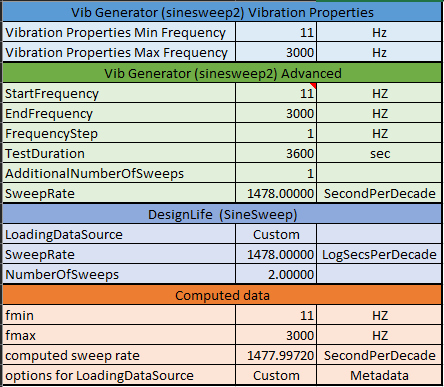
- 1.3.5.3.10. Vibration Generator to DesignLife for Frequency Range (Sine Sweep)
A fundamental understanding of standalone DesignLife is necessary to understand these settings. The information in this section does not apply to using the add-on.
Below is an example loading for Single Frequency analysis in the embedded add-on.
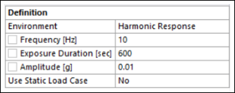
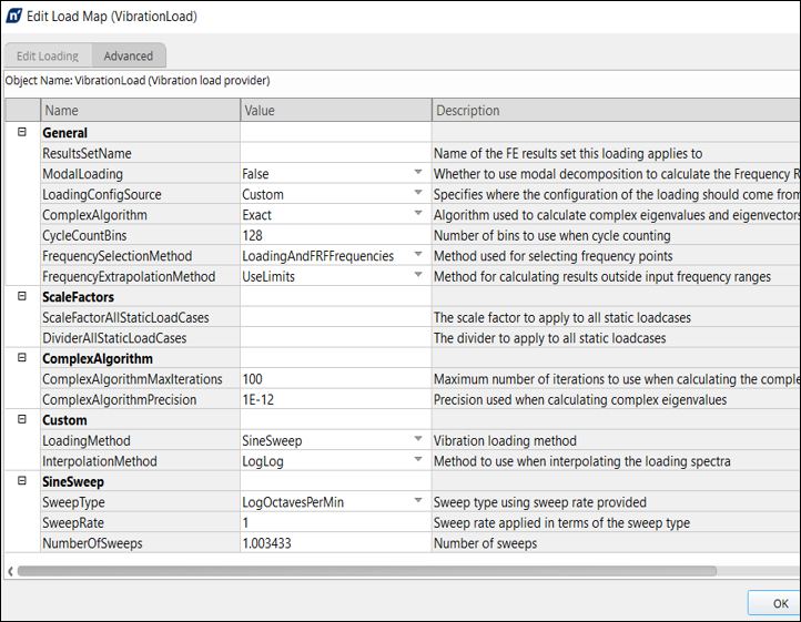
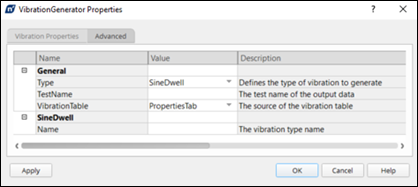
This is the equivalent DesignLife Integrated Vibration Generator configuration. In the Advanced tab, define the Type as .
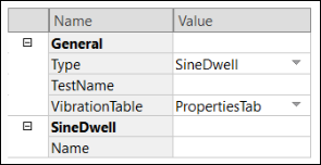
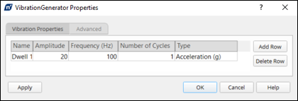
The table defined is as below.
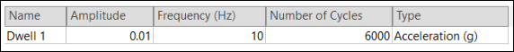
The main difference in the two approaches is the Exposure Duration property, which is not explicitly defined in the Integrated workflow. The general rule is to multiply the Frequency and Exposure Duration from the add-on load provider and use the product as input to the Number of Cycles field in the Vibration Generator Glyph.
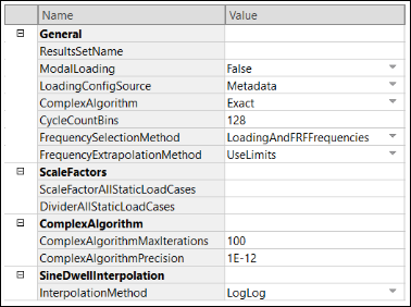
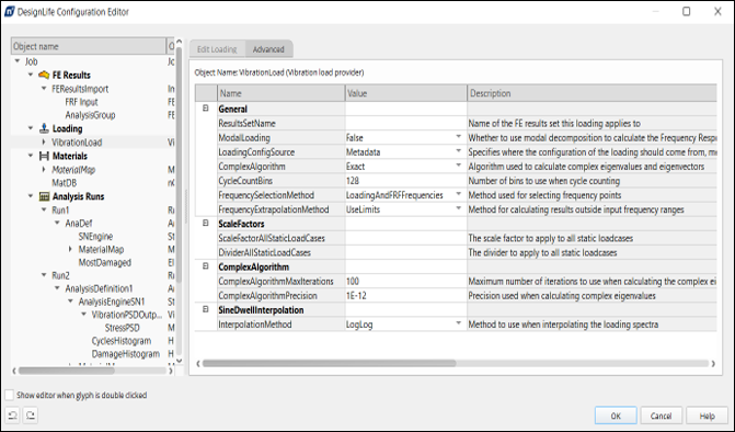
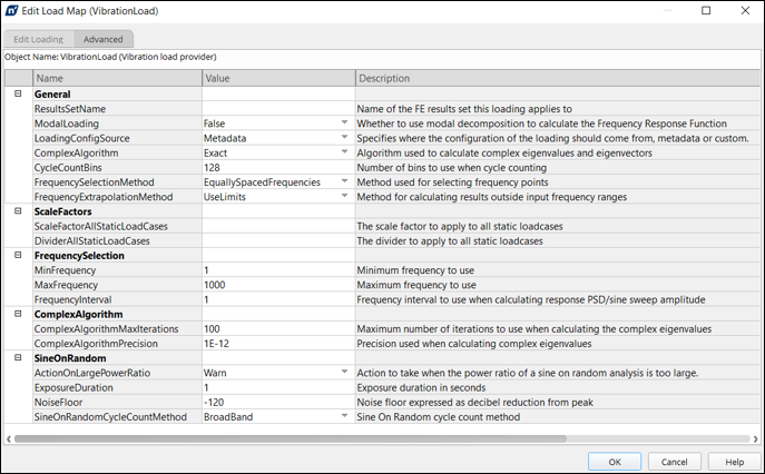
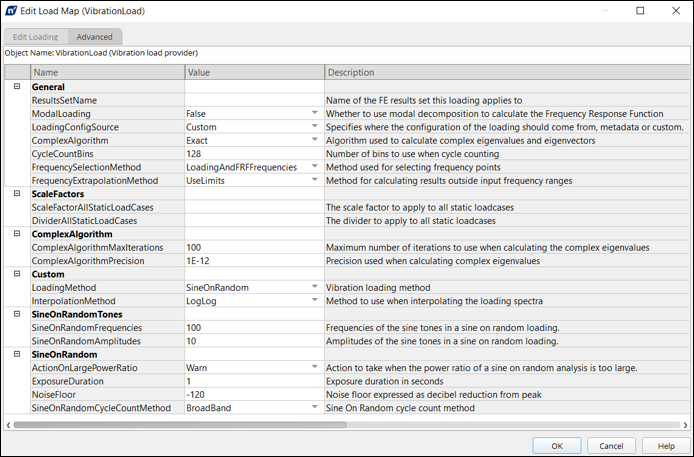
Go to the Vibration Load in the Analysis Glyph and ensure that the LoadingConfigSource field is set to .
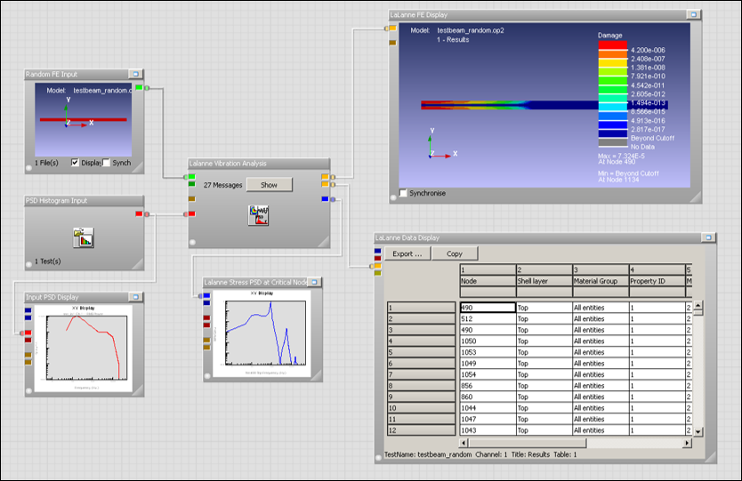
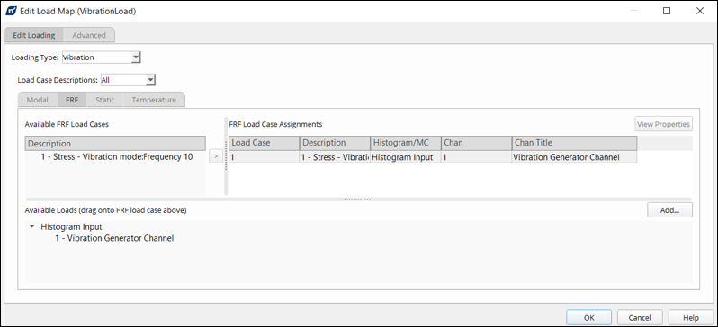
Below is an example of Frequency Range loading in a vibration fatigue analysis in the embedded add-on.
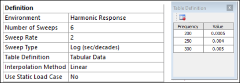
This is the equivalent DesignLife Integrated Vibration Generator configuration. In the Advanced tab, define the Type as .
In the Vibration Generator Configuration, additional inputs are required to the StartFrequency and EndFrequency fields. This would correspond to the frequency range defined in the upstream Harmonic analysis. The AdditionalNumberOfSweeps field is not equivalent to the Number of Sweeps field in the embedded add-on load. The equivalence depends on SweepType used (see the sections below for more information).
Go to the Load Provider option in the Analysis Glyph and set LoadConfigSource to .
The excitation applied in the steady state dynamics FE analysis as a frequency sweep with ‘unit’ magnitude
Force
Acceleration
Displacement
must match both model units and the input PSD units.
- PSD g2/Hz
9810 mm/sec2
9.81 m/sec2
386.4 in/sec2
32.2 ft/sec2
- PSD (mm/sec2)2/Hz
1.0 mm/sec2
0.001 m/sec2
- PSD (m/sec2)2/Hz
1000.0 mm/sec2
1.0 m/sec2
- PSD (in/sec2)2/Hz
25.4 mm/sec2
1.0 in/sec2
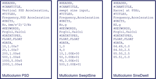
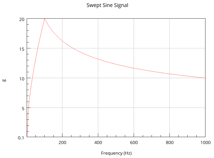
PSD and Swept Sine Inputs
- Multicolumn Input
CSV File
PSD
Swept Sine
Sine Dwell
EXCEL
- PSD Input
Vibration Generator
PSD
Swept Sine
Swept Sine 2
ASCII Translate
- CSV Multicolumn Inputs
Units used for display, not for conversion
Data values used directly by DesignLife
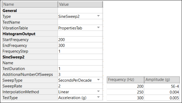
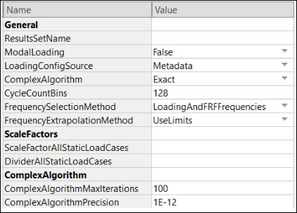
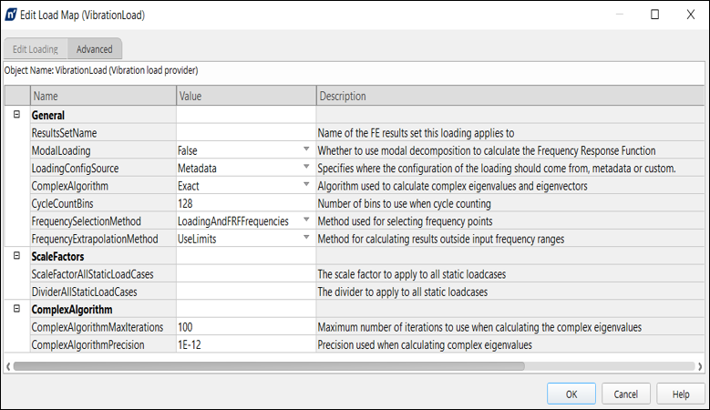
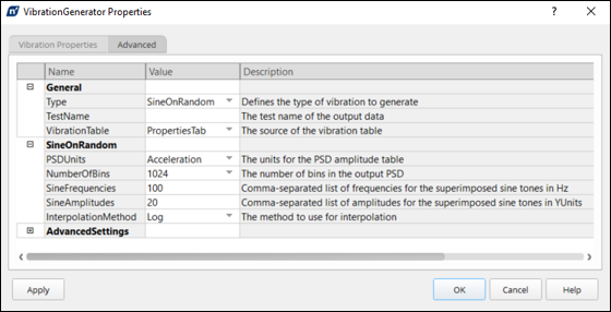
Advanced tab
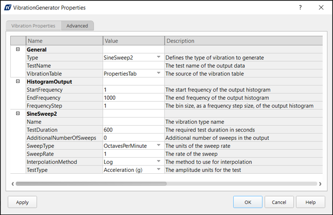
All properties on this form are passed out as metadata (as described in the image above):
General
SineSweep2 - Sets the vibration type
Histogram Output
StartFrequency
EndFrequency
FrequencyStep
Sinesweep2
TestDuration
AdditionalNumberOfSweeps
SweepType
SweepRate
InterpolationMethod
TestType
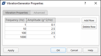
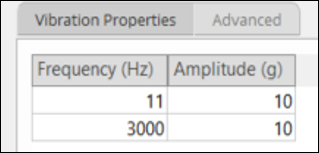
Vibration Properties tab
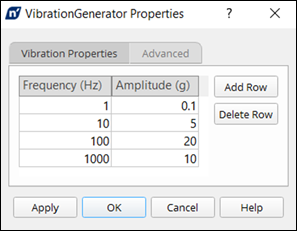
Data in the Vibration Properties tab is set manually and the
data in this table is passed out as metadata as a packet named
VibrationTables.
This table is defined on the Advanced tab by:
Type = SineSweep2
VibrationTable = PropertiesTab
TestType = Acceleration (g)
Metadata Example:
<Set name="VibrationGenerator1_Properties">
<Item name="AdditionalNumberOfSweeps" type="Long" value="0"/>
<Item name="EndFrequency" type="Float" value="1000"/>
<Item name="FrequencyStep" type="Float" value="1"/>
<Item name="InterpolationMethod" type="String" value="Log"/>
<Item name="StartFrequency" type="Float" value="1"/>
<Item name="SweepRate" type="Float" value="1"/>
<Item name="SweepType" type="String" value="OctavesPerMinute"/>
<Item name="TestDuration" type="Float" value="600"/>
<Item name="TestType" type="String" value="Acceleration (g)"/>
<Item name="Type" type="String" value="SineSweep2"/>
<Item name="VibrationTable" type="String" value="PropertiesTab"/>
<Item name="XMLTables" type="String" value=“VibrationGenerator1_Properties"/>

<VibrationTables Version=""1.0"">
 <Tables>
  <SineSweep2>
   <SineSweep2Item Amplitude=""0.1"" Frequency=""1""/>
   <SineSweep2Item Amplitude=""5"" Frequency=""10""/>
   <SineSweep2Item Amplitude=""20"" Frequency=""100""/>
   <SineSweep2Item Amplitude=""10"" Frequency=""1000""/>
  </SineSweep2>
 </Tables>
</VibrationTables>
Acceleration Histogram
The histogram output is controlled by the following Advanced tab properties:
StartFrequency
EndFrequency
FrequencyStep
The amplitudes for the histogram are obtained from the table on the Vibration Properties tab.
Any output frequencies not covered by the table will be set to zero.
These zero amplitudes will generate an error if the InterpolationMethod is set to .
The FRF can be paired up with metadata from Vibration Generator (see below).
When LoadingConfigSource is set to (see below), the swept sine definition in DesignLife is calculated from the Vibration Generator metadata properties.
The histogram from the Vibration Generator is not used, the sweep range is defined by the XMLTable in the metadata.
When LoadingConfigSource is set to , the swept sine definition in DesignLife is calculated from the Vibration Generator histogram and properties set on the Advanced tab.
When the LoadingConfigSource is switched from to and then back to , load provider properties are set to those calculated from the Vibration Generator settings.
If the frequency ranges defined on the Advanced tab and Vibration Properties tab of the Vibration Generator were not the same, a run and a run will generate different results.
Swept Sine Sweep Rate Calculations
- Linear HZ per Sec
Sweep_Rate = (fmax – fmin)/Time(sec)
- Log Secs per Decade
Sweep_Rate = Time(sec)/( log(fmax) – log(fmin) )
- Log Octaves per Min
Sweep_Rate = ( ( log(fmax) – log(fmin))/log(2) )/Time(min)
where,
Time = total duration of test
fmin = starting frequency of sweep in Hz
fmax = ending frequency of sweep in Hz
Sweep_Rate = sweep rate in sweep rate type
SineDwell properties are set for:
Amplitude
Frequency
Number of Cycles
These are passed out as metadata, with no histogram data output.
Amplitude from metadata
Advanced Tab
LoadingConfigSource must be set to .
The analysis uses amplitude, frequency and number of cycles from the Vibration Generator metadata.
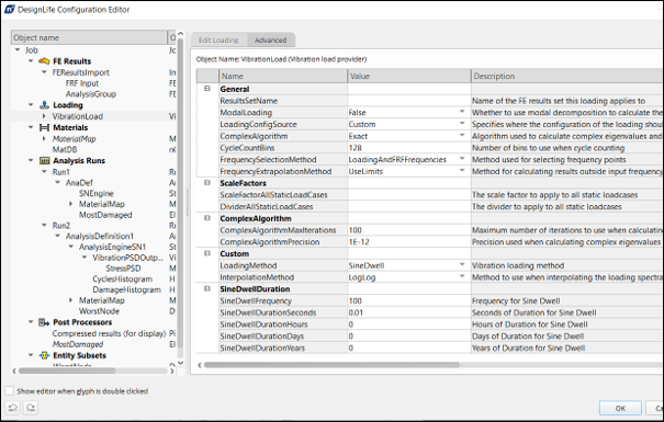
The DesignLife load provider must be set to the appropriate amplitude, SineDwellFrequency and SineDwellDurationSeconds.
Edit Loading Tab
The FRF (Frequency Response Function) is paired up with acceleration data. Load data can be multicolumn or histogram curves of acceleration amplitude versus frequency. The dwell frequency must be inside the range of the sine sweep contained in the load data.
Advanced Tab
SineDwell Properties
Frequency
Duration
The duration is the summation of:
SineDwellDurationSeconds
SineDwellDurationHours
SineDwellDurationDays
SineDwellDurationYears
When LoadConfigSource is set to , the dwell amplitude is determined from the sine sweep loading selected on the Edit Loading tab.
SineDwellDurationSeconds = (Number of Cycles)/(Frequency (Hz))
where Number of Cycles & and Frequency are set in the Vibration Generator.
PSD (Power Spectral Density) is defined in Vibration Properties.
Metadata 4 frequency points
Histogram 1024 frequency points
SineFrequencies and SineAmplitudes are output as metadata.
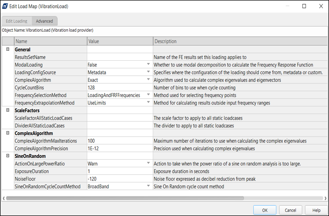
Advanced Tab
PSD is input from metadata containing 4 frequency steps.
Amplitudes and frequencies of sine tones are input as metadata.
ExposureDuration and CycleCountingMethod are DesignLife properties.
The default frequency selection method is used if:
Direct FRF did not contain well spaced frequencies
Answers were significantly different from the solution
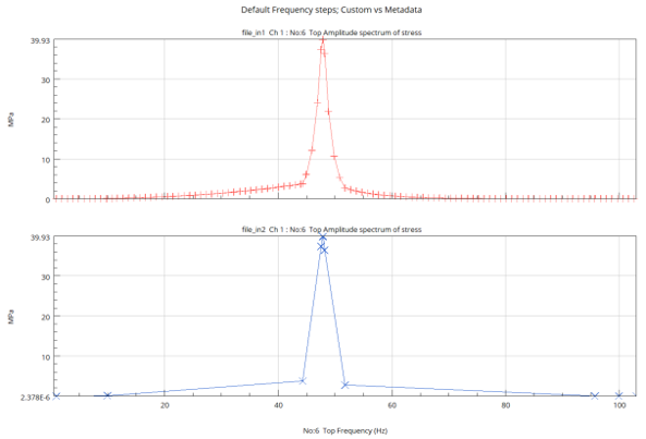
Frequency Steps used in Solution
In the example below, the default frequency selection method was initially used, but the PSD frequency steps from metadata and the FRF frequency steps from the harmonic solution did not have enough resolution to define the stresses.
Switching the FrequencySelectionMethod to , and specifying a 1 Hz frequency step corrected the issue (see below).
Advanced Tab
The lack of resolution in the frequency steps (above) was not immediately obvious.
Use of a modal FRF with fine frequency spacing is recommended.
Though the loading input is still from the Vibration Generator, with the setting selected the only input is the PSD as a histogram.
This makes the default frequency selection method an adequate choice.
As before, the and are both DesignLife properties.
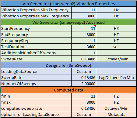
Below is the table conversion to see the DesignLife properties when setting the Vibration Generator.
- Linear HZ per Sec
Sweep_Rate = (fmax – fmin)/Time(sec)
- Log Secs per Decade
Sweep_Rate = Time(sec)/( log(fmax) – log(fmin) )
- Log Octaves per Min
Sweep_Rate = ( ( log(fmax) – log(fmin))/log(2) )/Time(min)
where,
Time = total duration of test
fmin = starting frequency of sweep in Hz
fmax = ending frequency of sweep in Hz
Sweep_Rate = sweep rate in sweep rate type
See examples of conversions below:
Linear (Hz/sec)
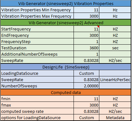
Log (sec/decades)
Log (octaves/minute)