


To specify loads for Frequency Domain Loading Events:
Click Add Load under Loading Event to add a load of type (Power Spectral Density), , , or to an event:
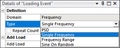
Alternatively, you can right-click Loading Event and choose .
A frequency-based load (, , or ) allows you to select .rst files from Harmonic and Modal systems.
To select the .rst directly from a connected upstream system, set the RST Definition to (default). You can then choose the upstream connected environment from which the .rst file will be selected.
If you want to load an .rst file manually, set the RST Definition to . Load the file from the , or load the file to the user_files folder inside the solver directory using the option.
Note: Manual file selection does not allow the use of .rst files from harmonic systems. If the RST Definition is set to , the .rst file must be from a Modal system and a Harmonic system must be linked using the or option for the MCF Environment property.
If you select , the file from that exact location is consumed. If this file is modified, the changes are consumed when solving, so ensure the required file is located at the absolute path. If you select , all loaded .rst files are copied to the user_files folder. If you are loading more than one .rst file, you must therefore give them different names, or they will be overwritten.
If a environment is selected, the MCF Environment setting is hidden and Direct FRF analysis will be performed.
If a environment is selected, the setting appears. Select between or or options.
- Manual File
Set the option to to import the required Modal Coordinate File (MCF). If you want the file to be local to your machine, load it as . If you want the file to be contained within the project, load it as .
Note that if is used, the imported file is copied to the user_files directory. Therefore, if you are importing multiple files, make sure they are named differently.
Note that you are loading a Modal Coordinates File (MCF) that can have different unit systems from the rst file of the Modal system. You therefore need to input the Units with which the MCF was generated so that the appropriate conversion is done.
- Environment
Set the option to to select the linked Harmonic system from where the MCF file is picked.
Environment and Harmonic Step entries appear and Modal Based FRF analysis will be performed. Select the required MCF Environment from the drop-down list generated with all Harmonic systems.
Note: The MCF File used by DesignLife should be mass normalized. This is the default in Mechanical.
Caution: The signs of the modal coordinates stored in the .mcf file are not unique. To ensure the mode shapes of the .rst and .mcf files are identical, they must be generated from the same analysis solution. Matching .rst and .mcf files from different solutions can produce incorrect results. If the .mcf file is imported, you must verify that it was generated from the same solution as the .rst file.
If the Analysis Settings for the selected Harmonic has the Multiple Steps option set to , the Harmonic Step entry will be hidden, as there is just a single step.
If the Analysis Settings for the selected Harmonic has the Multiple Steps option set to , the Harmonic Step will be visible and the list will be populated with all the steps defined in the Harmonic Analysis Settings.
If the Analysis Settings for the selected Harmonic has the Cluster Results option set to , you should see the following warning: Clustering frequencies in harmonic analysis is not recommended for vibration fatigue. Check results carefully.
For , and loading types, the Frequency Selection Method is exposed to allow you to define the method used for selecting the frequency points of the local response PSD or sine sweep amplitude.
The following options are available:
- LoadingAndFRFFrequencies
This is the default value. Use all the frequencies that appear in the loading PSD or sine sweep amplitude and the FRF. This is the default choice because it allows peaks in the loading and natural frequency response to be considered without loss in resolution.
- LoadingFrequencies
Use the same frequency values as the input loading PSD or sine sweep amplitudes.
- FRFFrequencies
Use the same frequency values as the FE analysis (the same frequencies as the FE Frequency Response Function). In the case of the multi-PSD input, all frequency values, in all configured load cases from the FE input will be used.
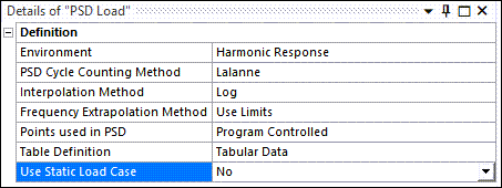
Details for PSD load are defined in the Details Window:
- Environment
Select the system from which the .rst file will be picked for the nCode fatigue analysis.
- PSD Cycle Counting Method
Select between Lalanne, Dirlik, Narrow Band, or Steinberg.
Note: If there is more than one loading event, all PSD loads must use the same PSD Cycle Counting Method.
- Interpolation Method
Select between or interpolation methods. The default is .
This will impact both the frequency while stepping through the FRF and the PSD points defined in the table. Therefore, it will modify both the PSD points in the csv frequency table and the InterpolationMethod in the input.dcl.
When the local response is calculated at frequencies where the FRF or PSD loading is not defined, the necessary values are interpolated. Interpolation can be LogLog (Log-Log) or LinLin (Linear-Linear). Note that if data is required beyond the ends of the data, the last data point is used.
- Frequency Extrapolation Method
Method for calculating results outside input frequency ranges. is the default value.
Select to perform all calculations within a frequency range valid for all inputs. Frequencies outside this range are ignored.
If you select to include frequencies outside the range of the input data, the last defined data point will be used.
- Points used in PSD
Select between , in which 1024 points are used, and in which you input the desired number of interpolation points.
- Table Definition
Click and enter the PSD spectrum values into the table. The spectrum values are the Frequency versus the loading squared per unit frequency. The Value in the table depends on the loading type. The loading type can be either force, displacement, velocity, or acceleration, but it must match the applied loading from the Harmonic analysis. For example, if the applied harmonic loading was 1G acceleration, then the PSD spectrum values must be defined in G^2/Hz.
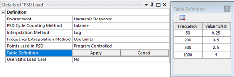
The table entries cannot have negative values or multiple entries for the same frequency value.
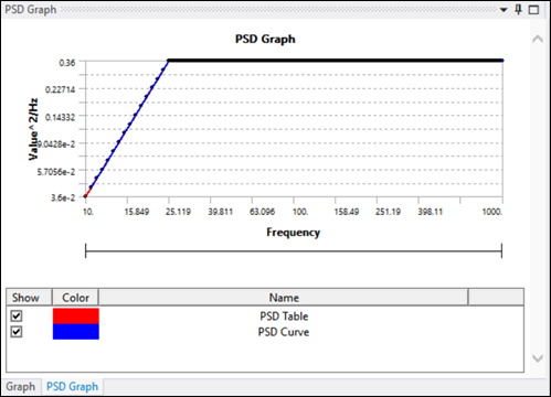
When selecting the PSD load, two curves are displayed in the PSD Graph window (see below), the PSD Table and the PSD Curve:
The PSD Table corresponds to the PSD spectrum versus the loading squared per unit values input in the tabular data table.
The PSD Curve corresponds to the interpolation performed on the input tabular data points, which depends on the Interpolation Method selected, the number of points used in PSD, and the input tabular data.
- Use Static Load Case
If Use Static Load Case is set to
Yes. Select the static environment and its step from which to consider the static load case.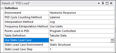
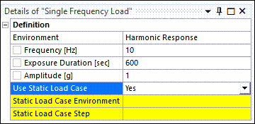
Details for load are defined in the Details Window:
- Environment
Select the system from which the .rst file will be picked for the nCode fatigue analysis.
- Frequency (Hz)
Set the frequency in Hz to a float positive value. The default value is 10 Hz. This parameter corresponds to the
SineDwellFrequencyparameter in nCode.- Exposure Duration (sec)
Set the exposure duration in seconds to a float positive or equal to a zero value. The default value is 600 sec. This parameter corresponds to the
SineDwellDurationSecondsparameter in nCode.- Amplitude (g)
Set the amplitude in g to a positive float value. This parameter is used to create the table file containing the Frequency [Hz] versus Amplitude [g] values that the Single Frequency load uses.
- Use Static Load Case
If Use Static Load Case is set to , select the static environment and its step from which to consider the static load case.
Details for load are defined in the Details Window:
- Environment
Select the system from which the .rst file will be picked for the nCode fatigue analysis.
- Number of Sweeps
How many times the spectrum of frequencies will be swept.
- Sweep Rate
The velocity of the frequency sweep, defined in the units set in the Sweep Type property.
- Sweep Type
The type of units that define the Sweep Rate. Choose between , , and .
- Interpolation Method
Choose between or interpolation methods.
The default value is . This will impact both the frequency stepping through the FRF and the PSD points defined in the table. Therefore, it will modify both the PSD points in the csv frequency table and the
InterpolationMethodin the input.dcl.When the local response is calculated at frequencies where the FRF or PSD loading is not defined, the necessary values are interpolated. Interpolation can be LogLog (Log-Log) or LinLin (Linear-Linear). Note that if data is required beyond the ends of the data, the last data point is used.
- Use Static Load Case
If Use Static Load Case is set to , select the static environment and its step from which to consider the static load case.
Details for load are defined in the Details Window:
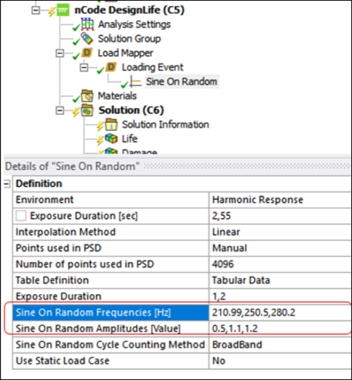
- Environment
Select the system from which the .rst file will be picked for the nCode fatigue analysis.
- Exposure Duration (sec)
Set the exposure duration in seconds to a float positive or to a zero value. This parameter corresponds to the
ExposureDurationparameter in the input.dcl.- Interpolation Method
Select between or interpolation method. The default value is .
This will impact both the frequency stepping through the FRF and the PSD points defined in the table. It will therefore modify both the PSD points in the csv frequency table and the
InterpolationMethodin the input.dcl.When the local response is calculated at frequencies where the FRF or PSD loading is not defined, the necessary values are interpolated. Interpolation can be LogLog (Log-Log) or LinLin (Linear-Linear). Note that if data is required beyond the ends of the data, the last data point is used.
- Table Definition
This corresponds to the PSD definition that will be used to generate the frequency table csv file.
- Sine On Random Frequencies [Hz]
This is a string property that contains a delimited list of sine tone frequencies to superimpose on the Random PSD for SineOnRandom vibrations.
This list must be the same length as the SineAmplitudes list. The values from the two lists are used in pairs. The default value is not set.
- Sine On Random Amplitudes [Value]
This is a string property that contains a delimited list of sine tone amplitudes to superimpose on the Random PSD for SineOnRandom vibrations.
This list must be the same length as the SineFrequencies list. The values from the two lists are used in pairs. The default value is not set.
Note: For the Sine On Random Frequencies and Sine On Random Amplitudes value lists, comma ',' can be used as the value separator unless working in a locale where comma is used as the decimal separator, in which case semi-colon ';' must be used instead.
- Sine On Random Cycle Counting Method
This property defines the underlying assumption to use in the cycle counter. The narrow band approach tends to be conservative and is the default. The broad band method is analogous to Gaussian random noise, is less conservative and is more in agreement with results obtained from time domain equivalent calculations. The default value is .
- Use Static Load Case
If Use Static Load Case is set to , select the static environment and its step from which to consider the static load case.
Note: If the Analysis Domain is set to , only Time Domain loads are allowed. If the Analysis Domain is set to , only Frequency Domain loads are allowed.
Note: If the Loading Type is set to , all loading events must be PSD too. PSD Loading events cannot be combined with other types of loading events. In addition, all PSD loading events, must have the same PSD Cycle Counting Method.
The EntityDataType is a property passed to the nCode solver through the input.dcl file that defines the type of results data that will be recovered from the input FE file(s).
Possible values are as follows:
- Vibration
Vibration results are required to support the Vibration Load Provider in order to make fatigue calculations based on PSD, swept-sine, sine-dwell, sine-on-random or multi-PSD loadings. The nCode solver looks in the FE results for a stress frequency response function (FRF). This takes the form of a complex stress response to unit excitation at a number of frequencies. Because the FRF will be combined with a PSD or swept-sine definition in the Vibration Load Provider to generate the local response, the unit excitation and the PSD of swept-sine should have consistent units. For example, for a PSD loading, if the PSD is defined in acceleration units of g2/Hz, then the FE analysis should provide the frequency response to an excitation of amplitude of 1g across the frequency range.
The EntityDataType is set to when consuming harmonic RST results for Stress, Strain, Gray Iron, Solid Seam Weld, Spot Weld and Short Fiber Composites analysis.
- ModalVibration
Vibration results are required to support the Vibration Load Provider in order to make fatigue calculations based on PSD, swept-sine, sine-dwell, sine-on-random or multi-PSD loadings. The nCode solver can use a stress frequency response function (FRF) directly (see above) but the FRF can also be calculated from modal stress results and this can be a more efficient solution.
A modal stress result consists of stress for each mode (real) and when combined with a set of modal participation factors (complex) is used to calculate the complex FRF. The modal stress result will typically be a much smaller result than the FRF, having stress results only for each mode of the system. The required frequency resolution of the FRF is obtained from the resolution of the modal participation factors.
The EntityDataType is set to when consuming modal RST results and harmonic MCF results for Stress, Strain, Gray Iron, Solid Seam Weld, Spot Weld and Short Fiber Composites analysis.
- ForceVibration
This option is used for Shell Seam Weld analyses based on vibration loading with forces and moments.
The EntityDataType is set to when consuming harmonic RST results for Shell Seam Weld analysis.
- ModalForceVibration
This option is used for Seam Weld analyses based on vibration loading with forces and moments. This is the modal equivalent of for seam welds.
A modal force result consists of forces for each mode (real) and when combined with a set of modal participation factors (complex) is used to calculate the complex FRF. The modal force result will typically be a much smaller result then the FRF, having force results only for each mode of the system. The required frequency resolution of the FRF is obtained from the resolution of the modal participation factors.
The EntityDataType is set to when consuming modal RST results and harmonic MCF results for Shell Seam Weld analysis.