


*PART
Defines geometry bodies.
Card 1
HEADING = name of the body specified in the Mechanical environment.
Card 2
PID = ID of the part. It is set in the LS-DYNA solver and does not reflect the ID specified in the mesh definition of the model.
SECID = ID of the section keyword associated with the part (see *SECTION).
MID = ID of the material keyword associated with the part (see *MAT).
EOSID = ID of the equation of state associated with the material of this part (*EOS and *MAT). If there is no EOS keyword associated with this part then this parameter is set to 0.
HGID = ID of the hourglass keyword associated with the part (see *HOURGLASS). If there is no hourglass keyword associated with this part then this parameter is set to 0.
Note: When you insert a PART object using the Keyword Manager, setting the field Material defined in *Mat section to Program Controlled specifies that the solver use the material defined for the Mechanical part that the keyword object is scoped to. Alternatively, you have the option to choose from other materials that are defined in the system.
*SECTION_BEAM
Defines cross sectional properties for beam, truss, spot weld and cable elements.
Card 1
SECID = ID of the section.
ELFORM = 1 or 2 (default). ELFORM = 2 is set for user defined cross sections. The default element formulation option can be changed using the Section object found under Part on the LSDYNA Pre tab of LS-DYNA.
SHRF = 0.833 (default).
QR = 0, which LS-DYNA defaults to 2, quadrature rule is 2x2 Gauss. If the cross sectional area of the beam is complex or user-defined, this parameter becomes IRID and is assigned the negative value of the IRID parameter in the corresponding *INTEGRATION_BEAM keyword (see above for details).
CST = 2 for solid cross sections nand hollow cross sections (arbitrary user defined integration rule).
Card 2
for solid types or hollow cylinders
TS1 = width of beam. This refers specifically to the dimension at node 1.
TS2 = TS1. This refers specifically to the dimension at node 2.
TT1 = 1. Height of beam. This refers specifically to the dimension at node 1. Set to zero for circular solids.
TT2 = TT1. This refers specifically to the dimension at node 2. Set to zero for circular solids. These parameters are overwritten by the *INTEGRATION_BEAM defined for these types.
for general symmetric types
A = cross-sectional area.
ISS = Iyy, moment of inertia about the local s-axis.
ITT = Izz, moment of inertia about the local t-axis.
IST = Iyz.
J = Ixx.
The Section object found under Part on the LSDYNA Pre tab of LS-DYNA allows you to modify the default generated values .
In presence of line Bodies:
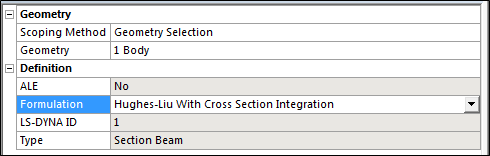
ELFORM = LS-DYNA ID from the Definition section of the Section object. This field is read only. The actual value of the element formulation is set by the Formulation section of the Section object.
If the formulation is one of the following, the Card is calculated similarly to the above definition for *SECTION_BEAM, and an *INTEGRATION_BEAM is written:
Hughes -Liu with cross section integration
Integrated warped beam
Belytschko Schwer full cross-section integration
Belytschko Schwer tubular beam with cross-section integration
If the formulation is one of the following:
Belytschko Schwer resultant beam (resultant)
Truss (resultant)
Belytschko Schwer full cross-section integration
Card 2 is modified and uses the syntax for the alternative form for formulations 2, 3, and 12.
STYPE is calculated from the section type defined in Ansys DesignModeler or SpaceClaim.
D1 - D6 are calculated from the dimensions defined in Ansys DesignModeler.
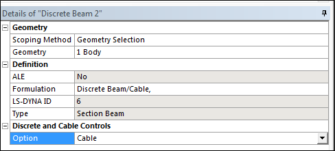
If the formulation is Discrete/ Beam Cable, an additional panel is available:
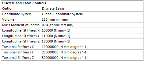
A material Card ( *MAT_LINEAR_ELASTIC_DISCRETE_BEAM ) is added to allow definition of properties for the discrete Beam.
*MAT_LINEAR_ELASTIC_DISCRETE_BEAM
This card replaces the material defined in Engineering and its properties are calculated from it and the above panel.
MID = ID of material type, must be unique between the material keyword definitions.
RO = Density of the Material
TKR = Longitudinal Stiffness X from Discrete and Cable Controls
TKS = Longitudinal Stiffness Y from Discrete and Cable Controls
TKT = Longitudinal Stiffness Z from Discrete and Cable Controls
RKR = Torsional Stiffness X from Discrete and Cable Controls
RKS = Torsional Stiffness X from Discrete and Cable Controls
RKT = Torsional Stiffness X from Discrete and Cable Controls
*MAT_CABLE_DISCRETE_BEAM
This card replaces the material defined in Engineering Data and its properties are calculated from it, and the above panel.
MID = ID of material type, must be unique between the material keyword definitions.
RO = Density of the Material
E = Young Modulus of the Material
A material Card (*MAT_CABLE_DISCRETE_BEAM) is added to allow definition of properties for the discrete Beam.
*SECTION_SHELL
Defines section properties for shell elements.
Card1
SECID = ID of the section.
ELFORM = 2 (default).
SHRF = 0.8333 (default).
NIP = 3 (default).
Card2
T1 = thickness of body.
T2-T4 = T1, shell thickness at nodes 2, 3 and 4.
The Section object found under Part on the LSDYNA Pre tab of LS-DYNA allows you to modify the default generated values .
In the presence of Surface Bodies:
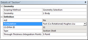
ELFORM = LS-DYNA ID from the Definition section of the Section object. This field is read only. The actual value of the element formulation is set by the Formulation section of the Section object.
NIP = Through Thickness Integration Points from the Definition section of the Section object.
*SECTION_SOLID
Defines section properties for solid elements.
Card
SECID = ID of the section.
ELFORM =
1 (default). Also, used for first-order hexahedral elements, 5-noded pyramids, 6-noded wedges or bodies with mixed element types that include tetrahedrons together with hexahedrons, pyramids, or wedges.
10 if elements are first-order tetrahedrons.
16 if the elements are second-order tetrahedrons.
The Section object found under Part on the LSDYNA Pre tab of LS-DYNA allows you to modify the default generated values.
The Method field determines the type of Section_Solid keyword that is written. A value of FEM indicates finite element formulations are available.
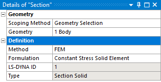
ELFORM = LS-DYNA ID from the Definition section of the Section object. This field is read only. The actual value of the element formulation is set by the Formulation section of the Section object.
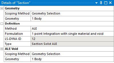
When Method is set to ALE, then the ALE specific formulations are available for selection. If the single material and void formulation is selected, then an additional geometry selection field is available to select the void bodies. The *INITIAL_VOID_PART card is created for these bodies.
*SECTION_SOLID_SPG
When the general setting Method is set to SPG, fields are provided to set section properties for an SPG body, in addition to the Geometry and Definition categories defined for all Section Solid objects.
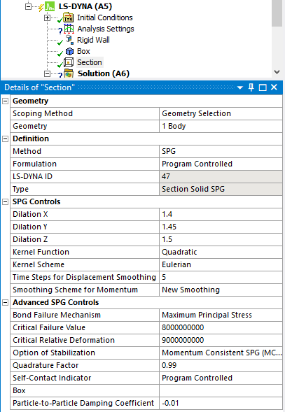
SPG Controls
DX, DY, DZ: Corresponds to the Dilation X, Y, Z values entered.
ISPLINE: Set by the Kernel Function field.
Kernel: Set by the Kernel Scheme field.
SMSTEP: Set from the Time Steps for Displacement Smoothing field.
MSC: Set from the Smoothing Scheme for Momentum field. The option New Smoothing can be set only if a feature flag called Enable Momentum Consistent SPG in Section Object is enabled (this is a change in behavior from the previous release).
Advanced SPG Controls
IDAM: Set from the Bond Failure Mechanism field.
FS: Set from the Critical Failure Value field.
STRETCH: Set from the Critical Relative Deformation field.
ITB: Set from the Option of Stabilization field. The option Momentum Consistent SPG (MCSPG) Formulation can be set only if a feature flag called Enable Momentum Consistent SPG in Section Object is enabled (this is a change in behavior from the previous release).
MSFAC: Set from the Quadrature Factor field.
ISC: Set from the Self-Contact Indicator field.
BOXID: Set from the Box field.
PDAMP: Set from the Particle-to-Particle Damping Coefficient field. This option is visible only if a feature flag called Enable Momentum Consistent SPG in Section Object is enabled (this is a change in behavior from the previous release).
To use a box, you must first add a Bounding Box object and then select that object in the Box field.
*SECTION_SOLID_FPD, *MAT_IFPD
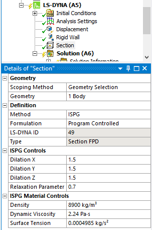
When Method is set to ISPG, categories are provided to set section properties for an ISPG body in addition to the Geometry and Definition categories defined for all Section Solid objects.
ISPG Controls
DX, DY, DZ: Corresponds to the Dilation X, Y, Z values entered
MCVISC: Set from the Relaxation Parameter field
ISPG Material Controls
The properties in this section correspond to fields in the *Mat_IFPD keyword.
RHO: Set from the Density field
MU: Set from the Dynamic Viscosity field
GAMMA: Set from the Surface Tension field
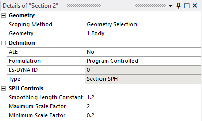
*SECTION_SPH
Defines section properties for SPH particles.
If you insert a Section object from the LSDYNA Pre tab and scope the section to a particle body, the SPH Controls section appears in the Details panel and includes 3 parameters as shown in the figure below:
Card
SECID: Section ID. SECID is referenced on the *PART card.
CSLH = Smoothing Length Constant from the Details panel: This constant is used to compute the initial smoothing length of the particles. It is defined as the ratio between the initial smoothing length and the spacing between particles. Values between 1.05 and 1.3 are acceptable. Using a value less than 1 is prohibited. Values larger than 1.3 will increase the computation time. The default value is 1.2.
Note: The smoothing length h(t) can vary over time with respect to the following inequality:
CSLH * H min < h(t) < CSLH * H max
To have a constant smoothing length over time, set H min = H max = 1.
HMIN = Minimum Scale Factor from the Details panel: The maximum scale factor for the smoothing length.
HMAX = Maximum Scale Factor from the Details panel:
SPHINI: Optional initial smoothing length. (Default is used.)
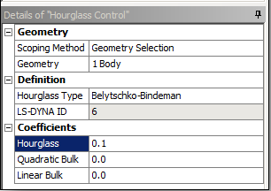
*HOURGLASS
Defines hourglass and bulk viscosity properties that are referenced in the *PART keyword using the HGID parameter (see the *PART keyword). The Hourglass Control object can be used to set the SPH part viscosity. You must scope an SPH body to the object and enter the Quadratic Bulk viscosity and the Linear Bulk viscosity.
This keyword can be written using the Hourglass Control object found under Part on the LSDYNA Pre tab of an LS-DYNA analysis, which allows you to specify body scoped hourglass definition.
HGID = ID of the part. It is set in the LS-DYNA solver and does not reflect the ID specified in the mesh definition of the model.
IHQ = Hourglass Control Type.
= 1 if the Hourglass Type is set to Standard LS-DYNA.
= 2 if the Hourglass Type is set to Flanagan-Belytschko Viscous Form.
= 3 if the Hourglass Type is set to Exact Volume Flanagan-Belytschko Viscous Form.
= 4 if the Hourglass Type is set to Flanagan-Belytschko Stiffness Form.
= 5 if the Hourglass Type is set to Exact Volume Flanagan-Belytschko Stiffness Form.
= 6 if the Hourglass Type is set to Belytschko-Bindeman.
= 7 if the Hourglass Type is set to Belytschko-Bindeman Linear Total Strain.
= 8 if the Hourglass Type is set to Full Projection Warping Stiffness
QM = Hourglass from the Coefficients section of the Hourglass Control object.
Q1 = Quadratic Bulk from the Coefficients section of the Hourglass Control object.
Q2 = Linear Bulk from the Coefficients section of the Hourglass Control object.
IBQ = 1 Standard LS-DYNA Bulk Viscosity
You can define the default values of the hourglass control type and coefficient from the Hourglass Controls section of the Analysis Settings (see *CONTROL_HOURGLASS).
This keyword can also be created using the Keyword Snippet (see also, Commands objects ) for the LS-DYNA solver. To use it, insert a Keyword Snippet under a Geometry body in the Tree Outline. The program will automatically substitute the HGID parameter in accordance with the *PART keyword of the associated body. All other parameters in the Keyword Snippet are transcribed literally.
If the keyword is entered in a Keyword Snippet anywhere else in the Tree Outline, it will be exported literally. This practice is not recommended, however, and a warning is provided in the header of Keyword Snippet objects when detected.
*CONSTRAINED_LAGRANGE_IN_SOLID
This keyword is used for reinforcements body interactions.
The first keyword paramter is set to the ID of the component containing line bodies.
The second keyword parameter is set to the ID of the component containing solid bodies.
This keyword is also used by the Coupling object.
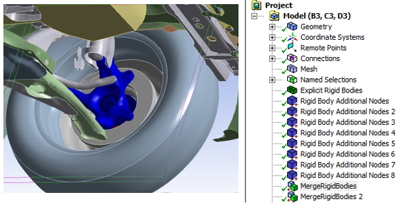
*CONSTRAINED_RIGID_BODIES
Specifies rigid bodies to be merged into one part. The resulting Part ID matches the ID of the rigid body designated as the target.
By constraining the rigid bodies together using a single multibody part you avoid specifying conflicting motion on the nodes shared among the rigid bodies. All boundary conditions applied to the target body will also be applied to all the contact bodies as well. Any boundary conditions that were applied to the contacts will be ignored.
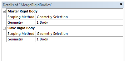
Card
PIDM = ID of the target rigid body.
PIDS = ID of the contact rigid body.
The object Master Rigid Body allows you to specify the target rigid body.
PID = the part ID of the rigid body.
NID = the set ID of additional nodes.
* CONSTRAINED_EXTRA_NODE_SET
The extra node set constraint type allows the addition of nodes (via a nodal component) to an existing rigid body. The nodal component that is added must not be attached to any other rigid body. The extra nodes that are added to a rigid body may be located anywhere in the model and may have coordinates outside those of the original rigid body. This option has many potential applications, including placing nodes where joints will be attached between rigid bodies, defining nodes where point loads will be applied, and defining a lumped mass at a specific location.
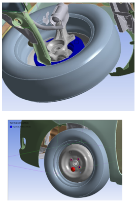
The underlying selected nodes will be part of the selected rigid body.
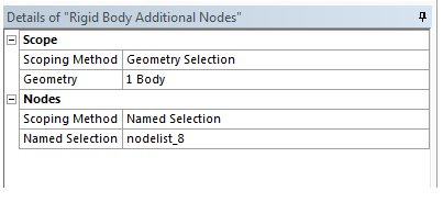
Card
PID = ID of the target rigid body.
NSID = ID of the set containing the selected nodes.