Equation of State (EOS) Keywords
The following are descriptions for *EOS keywords natively supported by LS-DYNA. More generally, any *EOS keyword may be introduced into the export file with the help of Commands objects in the Mechanical application (termed Keyword Snippet when referring to the LS-DYNA solver). To use it, insert a Keyword Snippet under a Geometry body in the Tree Outline. The program will automatically substitute the EOSID parameter, in accordance with the *PART keyword of the associated body. All other parameters in the Keyword Snippet are transcribed literally, overriding any values that would otherwise derive from the Engineering Data workspace.
If the *EOS keyword is entered in a Keyword Snippet anywhere else in the Tree Outline, it will be exported literally and the Engineering Data EOS information will also be exported, if present. This practice is not recommended, however, and a warning is provided in the header of Keyword Snippet objects when detected.
*EOS_GRUNEISEN
Specifies a shock equation of state. This keyword is created when a Shock EOS linear equation of state is present in the properties of a material that is used in the simulation and the Johnson Cook plasticity model is also present. The bilinear version of this equation of state is not currently supported.
Card 1
EOSID = ID of the keyword, must be unique between the *EOS keywords.
C = parameter C1 for a Linear Shock EOS property.
S1 = parameter S1 for a Linear Shock EOS property.
S2 = Parameter Quadratic S2 for a Linear Shock EOS property.
S3 = 0.
GAMAO = Gruneisen Coefficient for a Linear Shock EOS property.
A = 0.
Card 2 - mandatory, left blank.
*EOS_LINEAR_POLYNOMIAL
Specifies the coefficients for a linear polynomial elastic EOS. The *EOS_LINEAR_POLYNOMIAL keyword is only created when the Johnson Cook strength property is added to the material model (which requires an EOS), but no other EOS has been specified. It is not directly available from the Engineering Data workspace, however.
Card 1
EOSID = ID of the keyword, must be unique between the *EOS keywords.
C0 = 0.
C1 = Parameter A1.
C2 = Parameter A2.
C3 = Parameter A3.
C4 = Parameter A4.
C5 = Parameter A5.
C6 = Parameter A6.
Card 2 - mandatory, left blank.
*EOS_IDEAL_GAS
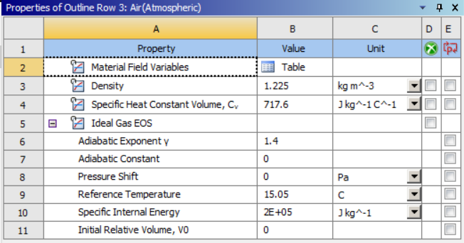
This keyword is created when an Ideal Gas EOS is present in the properties of a material that is used in the simulation. For the LS-DYNA system in Mechanical, the parameters Pressure Shift and Reference Temperature are not passed to the solver. Other fields are passed to the solver as indicated below. Density is used by the associated *MAT_NULL keyword.
Card 1
EOSID = ID of the keyword, must be unique between the *EOS keywords.
CV0 = Specific Heat Constant Volume, Cv.
CP0 = (Specific Heat Constant Volume Cv) × (Adiabatic Exponent 𝛄).
CL = 0.
CQ = 0.
T0 = (Specific Internal Energy) ÷ (Specific Heat Constant Volume, Cv).
V0 = Initial Relative Volume, V0.
VC0 = 0.
Card 2
ADIAB =
0: If Adiabatic Constant = 0.
1: If Adiabatic Constant ≠ 0.
*EOS_JWL
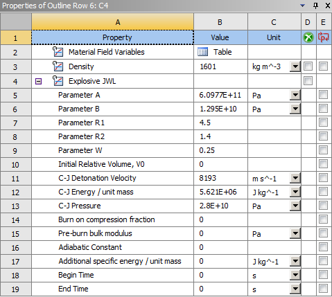
For the LS-DYNA system in Mechanical, the parameters Adiabatic Constant, Additional specific energy / unit mass, Begin Time, and End Time are not passed to the solver. Other fields are passed to the solver as indicated below. Some of these fields are used by the associated *MAT_HIGH_EXPLOSIVE_BURN keyword.
Card 1
EOSID = ID of the keyword, must be unique between the *EOS keywords.
A = Parameter A.
B = Parameter B.
R1 = Parameter R1.
R2 = Parameter R2.
OMEG = Parameter W.
E0 = (C-J Energy/unit mass) × Density.
V0 = Initial Relative Volume, V0.
Card 2a is left blank.
Card 2b is left blank.
Materials keywords
The following are descriptions for *MAT keywords natively supported by projects that use the LS-DYNA system. More generally, any *MAT keyword may be introduced into the project with the help of Commands objects in the Mechanical application (termed Keyword Snippet when referring to the LS-DYNA solver). To use it, insert a Keyword Snippet under a Geometry body in the Tree Outline. The program will automatically substitute the MID parameter in accordance with the *PART keyword (see below) of the associated body. All other parameters in the Keyword Snippet are transcribed literally, overriding any values that would otherwise derive from the Engineering Data workspace.
If the *MAT keyword is entered in a Keyword Snippet anywhere else in the Tree Outline, it will be exported literally and Engineering Data EOS information will also be exported, if present. This practice is not recommended, however, and a warning is provided in the header of Keyword Snippet objects when detected.
Note: When writing the optional Viscoelastic cards from the LS-DYNA analysis system a conversion is made to the Prony series terms. The Relative Moduli are converted to Shear\Bulk Moduli by applying the Initial Shear\Bulk Modulus as a scale factor, and the Relaxation Times are converted to Damping Coefficients by inversion.
|
Where:
|

Where:
|


The Initial Shear\Bulk Modulus for each material model is determined using the definition in Hyperelasticity in the Material Reference or using a specific input field in Engineering Data.
*MAT_3-PARAMETER_BARLAT
This material law is used for the Bilinear 3 Parameter Barlat hardening and exponential 3 parameter Barlat hardening models.
Card 1
MID = ID of the material. Must be unique between the material keyword definitions.
RO = density of the material from the Engineering Data workspace.
E = Young's modulus of the material from the Engineering Data workspace, either specified directly or calculated from Bulk and Shear moduli.
PR = Poisson's Ratio of the material from the Engineering Data workspace, either specified directly or calculated from Bulk and Shear moduli.
HR = Hardening Type, set to 2 for Swift or 5 for Ghosh when the model is exponential, or to 1 when the model is bilinear.
P1 = Material Parameter, set to Hardening Constant K from Engineering Data when the model is exponential, or to the tangent modulus when the model is bilinear.
P2 = Material Parameter, set to Hardening Exponent n from Engineering Data when the model is exponential, or to the yield stress when the model is bilinear.
ITER = Iteration flag, set to 0.
Card 2
M = Barlat exponent from Engineering data.
R00 = Lankford parameter in 0 degree direction.
R45 = Lankford parameter in 45 degree direction.
R90 = Lankford parameter in 90 degree direction.
Card 3
AOPT = Coordinate System ID of body Coordinate System in Mechanical.
C = Strain Rate Constant.
P = Strain Rate Constant.
EPSO = Reference Strain Rate.
*MAT_BARLAT_ANISOTROPIC_PLASTICITY
Card 1
MID = ID of the material. Must be unique between the material keyword definitions.
RO = density of the material from the Engineering Data workspace.
E = Young's modulus of the material from the Engineering Data workspace, either specified directly or calculated from Bulk and Shear moduli.
PR = Poisson's Ratio of the material from the Engineering Data workspace, either specified directly or calculated from Bulk and Shear moduli.
k = Hardening Constant from Engineering Data
n = Hardening Exponent from Engineering Data
m = Barlat Exponent from Engineering Data
e0 = Initial Yield Strain From Engineering Data
Card 2
A = Barlat Anisotropic Coefficient A from Engineering data.
B = Barlat Anisotropic Coefficient B from Engineering data.
C = Barlat Anisotropic Coefficient C from Engineering data.
F = Barlat Anisotropic Coefficient F from Engineering data.
G = Barlat Anisotropic Coefficient G from Engineering data.
H = Barlat Anisotropic Coefficient H from Engineering data.
Card 3
AOPT = Coordinate System ID of body Coordinate System in Mechanical.
*MAT_ADD_EROSION
ADD_EROSION is added to a given material when a failure model is defined in Engineering Data, to a material that doesn't support the defined failure model.
Card
MID = ID of material for which this failure model applies.
SIGP1 = Principal Stress Failure , if present. Otherwise it is 0.
MXEPS = Maximum Principal Strain , if present. Otherwise it is 0.
EPSSH = Maximum Shear Strain , if present. Otherwise it is 0.
EFFEPS = Maximum Equivalent Plastic Strain EPS , if present. Otherwise it is 0.
MNPRES = Maximum Tensile Pressure , if present. Otherwise it is 0.
*MAT_ARRUDA_BOYCE_RUBBER (or *MAT_127)
MID = ID of the material type. Must be unique between the material keyword definitions.
RO = Density of the material from the Engineering Data workspace.
K = Bulk modulus of the material, calculated from incompressibility parameter.
G = Initial shear modulus of the material from the Engineering Data workspace.
Optional Viscoelastic Constants Cards
These optional cards will be written if the constants have been defined using the Prony Shear Relaxation properties in Engineering Data
*MAT_BLATZ-KO_RUBBER (or *MAT_007)
Blatz-Ko materials are only for rubber materials under compression.
Poisson's ratio (NUXY) is automatically set to 0.463 by LS-DYNA, so only DENS and GXY are required.
Card1
MID = ID of the material type. Must be unique between the material keyword definitions.
RO = Density of the material.
G = Initial Shear modulus of material.
*MAT_ELASTIC (or *MAT_001)
Specifies isotropic elastic materials. It is available for beam, shell and solid elements. This keyword is used if the selected material includes the Isotropic Elasticity strength model and the Stiffness Behavior is set to Deformable in the Definition section of the body.
Card
MID = ID of material type. Must be unique between the material keyword definitions.
RO = density of the material from the Engineering Data workspace.
E = Young's modulus of the material from the Engineering Data workspace, either specified directly or calculated from Bulk and Shear moduli.
PR = Poisson's ratio of the material from the Engineering Data workspace, either specified directly or calculated from Bulk and Shear moduli.
*MAT_ENHANCED_COMPOSITE_DAMAGE (or *MAT_054)
This material keyword is written for orthotropic materials when the shell layered composite damage model in Analysis Settings is set to Enhanced Composite Damage Model.
Card1
MID = ID of material type, must be unique between the material keyword definitions.
RO = density of material.
EA = Young's Modulus X direction from the Orthotropic Elasticity model.
EB = Young's Modulus Y direction from the Orthotropic Elasticity model.
EC = Young's Modulus Z direction from the Orthotropic Elasticity model.
PRBA = Poisson's Ratio XY from the Orthotropic Elasticity model multiplied by Young's Modulus Y / Young's Modulus X.
PRCA = Poisson's Ratio YZ from the Orthotropic Elasticity model multiplied by Young's Modulus Z / Young's Modulus X.
PRCB = Poisson's Ratio XZ from the Orthotropic Elasticity model multiplied by Young's Modulus Z / Young's Modulus Y.
Card2
GAB = Shear Modulus XY from the Orthotropic Elasticity model.
GBC = Shear Modulus YZ from the Orthotropic Elasticity model.
GCA = Shear Modulus XZ from the Orthotropic Elasticity model.
AOPT =
0 (default). When this parameter is set to zero the locally orthotropic material axes are determined from three element nodes. The first node specifies the local origin, the second specifies one of the axes and the third specifies the plane on which the axis rests.
- ID of local coordinate system assigned to the body with this material model.
Card 3 is left blank.
Card 4 is left blank.
Card 5 is left blank.
Card 6
XC = Compressive X of the Orthotropic Stress Limits definition, if present. Otherwise it is 0.
XT = Tensile X of the Orthotropic Stress Limits definition, if present. Otherwise it is 0.
YC = Compressive Y of the Orthotropic Stress Limits definition, if present. Otherwise it is 0.
YT = Tensile Y of the Orthotropic Stress Limits definition, if present. Otherwise it is 0.
SC = Shear XY of the Orthotropic Stress Limits definition, if present. Otherwise it is 0.
*MAT_HIGH_EXPLOSIVE_BURN
Allows for modeling of the detonation of a high explosive. This keyword is created when an Explosive JWL Equation of State is present in the properties of a material that is used in the simulation. It is used in conjunction with the *EOS_JWL keyword and uses some of the fields defined in the Explosive JWL property.
Card 1
MID = ID of material type, must be unique between the material keyword definitions.
R0 = Density.
D = C-J Detonation Velocity.
PCJ = C-J Pressure.
BETA =
0: if Burn on compression fraction ≠ 0.
2: if Burn on compression fraction = 0.
K = Pre-burn bulk modulus
G = 0.
SIGY = 0.
*MAT_LAMINATED_COMPOSITE_FABRIC
This material keyword is written for orthotropic materials when the shell layered composite damage model in Analysis Settings is set to Laminated Composite Fabric.
*MAT_FLD_TRANSVERSELY_ANISOTROPIC
This material law is used for the Bilinear transversely anisotropic hardening and multilinear transversely anisotropic hardening models.
Card1
MID = ID of material type, must be unique between the material keyword definitions.
RO = density of the material from the Engineering Data workspace.
E = Young's modulus of the material from the Engineering Data workspace, either specified directly or calculated from Bulk and Shear moduli.
PR = Poisson's ratio of the material from the Engineering Data workspace, either specified directly or calculated from Bulk and Shear moduli.
SIGY = Yield Strength.
ETAN = Tangent Modulus.
R = Anisotropic Hardening Parameter.
HLCID = 0 when the model is bilinear, or is set to the ID of the curve of effective stress versus plastic strain when the model is multilinear.
LCFLD is the ID of the curve describing the forming limit diagram.
*MAT_HYPERELASTIC_RUBBER (or *MAT_077_H)
Specifies a general hyperelastic rubber model, optionally combined with viscoelasticity. This keyword is used if the material includes the Mooney-Rivlin, Polynomial or Yeoh hyperelastic strength model and the Stiffness Behavior is set to Deformable in the Definition section of the body.
Card1
MID = ID of material type, must be unique between the material keyword definitions.
RO = density of the material from the Engineering Data workspace.
PR = Poisson's ratio of the material from the Engineering Data workspace. Values higher than 0.49 are recommended. Smaller values may not work and should not be used.
N = 0, specifies that the constants in card 2 will be defined.
NV = 0. This parameter is not used if N = 0 above.
G = Shear modulus of the material from the Engineering Data workspace.
SIGF = 0. This parameter is not used if N = 0 above.
Card2
C10 = constant C10 from the Engineering Data workspace.
C01 = constant C01 from the material properties in the Engineering Data. Set to zero for Yeoh models.
C11 = constant C11 from the Engineering Data workspace. Set to zero for Yeoh models.
C20 = constant C20 from the Engineering Data workspace.
C02 = constant C02 from the Engineering Data workspace. Set to zero for Yeoh models.
C30 = constant C30 from the Engineering Data workspace.
Optional Viscoelastic Constants Cards
These optional cards will be written if the constants have been defined using the Prony Shear Relaxation properties in Engineering Data
*MAT_JOHNSON_COOK (or *MAT_015)
Defines a Johnson - Cook type of material. Such materials are useful for problems with large variations in strain rates where adiabatic temperature increases due to plastic heating cause material softening. This keyword is used if the material specified includes a Johnson Cook strength model.
Card1
MID = ID of material type, must be unique between the material keyword definitions.
RO = density of material.
G = Shear modulus of material.
E = Young's modulus of the material (shell elements only).
PR = Poisson's ratio of the material (shell elements only).
Card2
A = Initial yield stress from the Johnson Cook strength parameters.
B = Hardening Constant from the Johnson Cook strength parameters.
N = Hardening Exponent from the Johnson Cook strength parameters.
C = Strain Rate Constant from the Johnson Cook strength parameters.
M = Thermal Softening Exponent from the Johnson Cook strength parameters.
TM = Melting Temperature from the Johnson Cook strength parameters.
TR = 15, room temperature.
EPSO = Reference Strain Rate from the Johnson Cook strength parameters.
Card3
CP = Specific Heat from the material properties.
PC = 0 (LS-DYNA default).
SPALL = 2.0 (LS-DYNA default).
IT = 0 (LS-DYNA default).
D1 = D1 parameter of the Johnson Cook failure model definition, if present. Otherwise it is 0.
D2 = D2 parameter of the Johnson Cook failure model definition, if present. Otherwise it is 0.
D3 = D3 parameter of the Johnson Cook failure model definition, if present. Otherwise it is 0.
D4 = D4 parameter of the Johnson Cook failure model definition, if present. Otherwise it is 0.
Card4
D5 = D5 parameter of the Johnson Cook failure model definition, if present. Otherwise it is 0.
C2/P = "Reference Strain Rate (/sec)" parameter of the Johnson Cook failure model definition, if present. Otherwise it is 0.
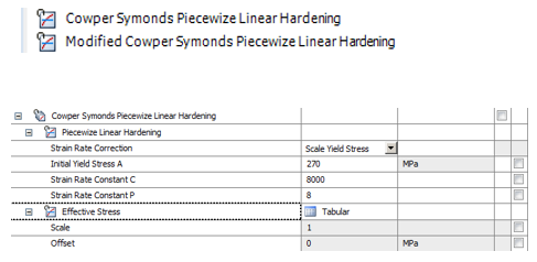
*MAT_MODIFIED_PIECEWISE_LINEAR_PLASTICITY (or *MAT_123)
Enhanced Piecewise Linear model (for shell elements only) that accounts for multiple failure methods:
Effective plastic strain.
Thinning (through-thickness) plastic strain.
Major principal in-plane strain.
You can specify the number of through-thickness integration points that must fail before the shell element is deleted. This model is useful in pure bending applications where the center layer may never reach failure strain.
Card 1
MID = ID of material type, must be unique between the material keyword definitions.
RO = density of material.
E = Young's modulus of the material.
PR = Poisson's ratio of the material.
SIGY = Yield Strength from the BISO strength model. It is not required for MISO models.
ETAN = Tangent Modulus from the BISO strength model. It is not required for MISO models.
FAIL = Maximum Equivalent Plastic Strain EPS parameter of the Plastic Strain failure model, if present. Otherwise it is set to 10E+20.
Card2
C = Strain Rate Constant C.
P = Strain Rate Constant P.
LCSS = ID of the curve defining effective stress versus effective plastic strain.
LCSR is left blank.
VP = Formulation for rate effects. Set VP to 0 if the strain rate correction is set to scale yield stress, set it to 1 if strain rate correction is set to viscoplastic.
EPSTHIN = Thinning Strain at Failure.
EPSMAJ = Major in Plane Strain At Failure.
NUMINT is left blank.
Card3 is left blank.
Card4 is left blank.
Card5 is left blank.
*MAT_NULL
Card 1
MID = ID of material type, must be unique between the material keyword definitions.
R0 = Density.
PC = 0.
MU = 0.
TEROD = 0.
CEROD = 0.
YM = 0.
PR = 0.
*MAT_OGDEN_RUBBER (or *MAT_077_O)
Specifies the Ogden rubber model, optionally combined with viscoelasticity. This keyword is used if the material includes the Ogden hyperelastic strength model and the Stiffness Behavior is set to Deformable in the Definition section of the body.
For card 1 see *MAT_HYPERELASTIC_RUBBER
Card2
MU1 = Material Constant MU1 from the Ogden model.
MU2 = Material Constant MU2 from the Ogden model.
MU3 = Material Constant MU3 from the Ogden model.
MU4 = 0.
MU5 = 0.
MU6 = 0.
MU7 = 0.
MU8 = 0.
Card3
ALPHA1 = Material Constant A1 from the Ogden model.
ALPHA2 = Material Constant A2 from the Ogden model.
ALPHA3 = Material Constant A3 from the Ogden model.
ALPHA1 = 0.
ALPHA1 = 0.
ALPHA1 = 0.
ALPHA1 = 0.
ALPHA8 = 0.
Optional Viscoelastic Constants Cards
These optional cards will be written if the constants have been defined using the Prony Shear Relaxation properties in Engineering Data
*MAT_ORTHOTROPIC_ELASTIC (or *MAT_002)
Specifies the model for an elastic-orthotropic behavior of solids, shells, and thick shells. This keyword is created when the Orthotropic Elasticity property is present in a material that is used. The Poisson's ratios required with this keyword must be in their minor version, however Workbench requires their major versions hence they are converted by multiplying them by the relevant Young's modulus ratios.
Card1
MID = ID of material type, must be unique between the material keyword definitions.
RO = density of material.
EA = Young's Modulus X direction from the Orthotropic Elasticity model.
EB = Young's Modulus Y direction from the Orthotropic Elasticity model.
EC = Young's Modulus Z direction from the Orthotropic Elasticity model.
PRBA = Poisson's Ratio XY from the Orthotropic Elasticity model multiplied by Young's Modulus Y / Young's Modulus X.
PRCA = Poisson's Ratio YZ from the Orthotropic Elasticity model multiplied by Young's Modulus Z / Young's Modulus X.
PRCB = Poisson's Ratio XZ from the Orthotropic Elasticity model multiplied by Young's Modulus Z / Young's Modulus Y.
Card2
GAB = Shear Modulus XY from the Orthotropic Elasticity model.
GBC = Shear Modulus YZ from the Orthotropic Elasticity model.
GCA = Shear Modulus XZ from the Orthotropic Elasticity model.
AOPT =
0 (default). When this parameter is set to zero the locally orthotropic material axes are determined from three element nodes. The first node specifies the local origin, the second specifies one of the axes and the third specifies the plane on which the axis rests.
- ID of local coordinate system assigned to the body with this material model.
Card3 - mandatory, left blank.
Card4 - mandatory, left blank.
*MAT_ANISOTROPIC_ELASTIC (or *MAT_002_ANIS)
Specifies the model for an elastic-anisotropic behavior of solids, shells, and thick shells. This keyword is created when the Anisotropic Elasticity property is present in a material that is used. Due to symmetry only the upper triangular Cij's need to be defined.
Card1
MID = ID of material type, must be unique between the material keyword definitions.
RO = density of material.
C11 = The 1, 1 term in the 6 × 6 anisotropic constitutive matrix.
C12 = The 1, 2 term in the 6 × 6 anisotropic constitutive matrix.
C22 = ⋮
C13 = ⋮
C23 = ⋮
C33 = ⋮
Card2
C14 = ⋮
C24 = ⋮
C34 = ⋮
C44 = ⋮
C15 = ⋮
C25 = ⋮
C35 = ⋮
C45 = ⋮
Card3
C55 = ⋮
C16 = ⋮
C26 = ⋮
C36 = ⋮
C46 = ⋮
C56 = ⋮
C66 = The 6, 6 term in the 6 × 6 anisotropic constitutive matrix.
AOPT =
0 (default). When this parameter is set to zero the locally orthotropic material axes are determined from three element nodes. The first node specifies the local origin, the second specifies one of the axes and the third specifies the plane on which the axis rests.
- ID of local coordinate system assigned to the body with this material model.
Card4 - mandatory, left blank.
Card5 - mandatory, left blank.
*MAT_PIECEWISE_LINEAR_PLASTICITY (or *MAT_24)
Defines elasto-plastic materials with arbitrary stress-strain curve and arbitrary strain rate dependency. This keyword is used if the material specified includes a Multilinear Isotropic Hardening (BISO or MISO) strength model.
Card1
MID = ID of material type, must be unique between the material keyword definitions.
RO = density of material.
E = Young's modulus of the material.
PR = Poisson's ratio of the material.
SIGY = Yield Strength from the BISO strength model. It is not required for MISO models.
ETAN = Tangent Modulus from the BISO strength model. It is not required for MISO models.
FAIL = Maximum Equivalent Plastic Strain EPS parameter of the Plastic Strain failure model, if present. Otherwise it is set to 10E+20.
Card2
C = Strain Rate Constant C when used in the Cowper Symonds Piecewise Linear Hardening Engineering Data Material, 0 otherwise.
P = Strain Rate Constant P when used in the Cowper Symonds Piecewise Linear Hardening Engineering Data Material, 0 otherwise.
LCSS = ID of the curve that defining effective stress versus effective plastic strain.
Card3 - mandatory, left blank.
Card4 - mandatory, left blank.
*MAT_PLASTIC_KINEMATIC (or *MAT_003)
Specifies isotropic and kinematic hardening plastic behavior in materials. This keyword is created when the Bilinear Kinematic Hardening (BKIN) strength model is present in a material.
Card1
MID = ID of material type, must be unique between the material keyword definitions.
RO = density of material.
E = Young's modulus of the material.
PR = Poisson's ratio of the material.
SIGY = Yield Strength from the BKIN strength model.
ETAN = Tangent Modulus from the BKIN strength model.
BETA = 0.
Card2
SRC = left blank.
SRP = left blank.
FS = Maximum Equivalent Plastic Strain EPS parameter of the Plastic Strain failure model, if present. Otherwise it is left blank.
*MAT_POWER_LAW_PLASTICITY (or *MAT_018)
Defines an isotropic plasticity model with rate affects modeled by a power hardening law. Power law hardening defined with strength coefficient k and hardening coefficient n .
Card1
MID = ID of material type, must be unique between the material keyword definitions.
RO = density of material.
E = Young's modulus of the material.
PR = Poisson's ratio of the material.
K = Strength coefficient.
N = Hardening exponent.
SRC = Strain rate parameter C. If zero, rate effects are ignored.
SRP = Strain rate parameter, P. If zero, rate effects are ignored.
Card 2
SIGY = Initial yield stress.
EPSF = Maximum Equivalent Plastic Strain EPS parameter of the Plastic Strain failure model, if present. Otherwise it is left blank.
VP = Formulation for rate effects. Set VP to 0 if the strain rate correction is set to scale yield stress. Set it to 1 if the strain rate correction is set to viscoplastic.
*MAT_RATE_SENSITIVE_POWERLAW_PLASTICITY (or *MAT_064)
This specialized model is used specifically for superplastic forming.
Card1
MID = ID of material type, must be unique between the material keyword definitions.
RO = density of material.
E = Young's modulus of the material.
PR = Poisson's ratio of the material.
K = Hardening Constant.
M = Hardening exponent.
N = Strain Rate Constant.
EO = Reference Strain Rate
VP = Formulation for rate effects. Set VP to 0 if the strain rate correction is set to scale yield stress. Set it to 1 if strain rate correction is set to viscoplastic
EPSO is left blank
*MAT_RIGID (or *MAT_020)
Specifies materials for rigid bodies. This keyword is created when the Stiffness Behavior is set to Rigid under the Definition section of the body. Any strength or EOS material properties defined are ignored.
Card1
MID = ID of material type, must be unique between the material keyword definitions.
RO = density of material.
E = Young's modulus of the material.
PR = Poisson's ratio of the material.
Card2
CMO =
0 if there are no constraints on the rigid body.
-1 if rigid body is constrained in any way.
CON1 =
0 if there are no constraints on the rigid body.
= Local Coordinate System ID if associated with the constraint. Otherwise it is set to 0.
CON2 =
0 if there are no constraints on the rigid body.
= 111111 if the body is constrained with a fixed support or with a combination of a simple support and a fixed rotation.
= 111000 if the body is constrained with a simple support.
= 000111 if the body is constrained with a fixed rotation.
Card3
LCO = CON1 if non-zero. Otherwise it will remain blank.
*MAT_SIMPLIFIED_JOHNSON_COOK (or *MAT_098)
Defines a Johnson - Cook type of material. Such materials are useful for problems with large variations in strain rates where adiabatic temperature increases due to plastic heating cause material softening. This keyword is used if the material specified includes a Johnson Cook strength model without an Equation Of State.
Card1
MID = ID of material type, must be unique between the material keyword definitions.
RO = density of material.
E = Young's modulus of the material.
PR = Poisson's ratio of the material.
Card2
A= Initial yield stress from the Johnson Cook strength parameters.
B = Hardening Constant from the Johnson Cook strength parameters.
N = Hardening Exponent from the Johnson Cook strength parameters.
C = Strain Rate Constant from the Johnson Cook strength parameters.
PSFAIL = Maximum Equivalent Plastic Strain EPS parameter of the Plastic Strain failure model, if present. Otherwise it is set to 10E+20.
SIGMAX = 0. Not used.
SIGSAT = 0. Not used.
EPSO = Reference Strain Rate from the Johnson Cook strength parameters.
*MAT_SPRING_INELASTIC
This material model is used for springs with a tension only or compression only behavior .
Card
MID = ID of material type. Must be unique between the material keyword definitions.
LCFD = ID for curve describing force versus displacement.
KU is unused.
CTF = flag for compression/tension behavior. It is set to -1.0 for tension only and to 1.0 for compression only.
*MAT_SPRING_NONLINEAR_ELASTIC
This material model is used for springs when the force versus displacement curve is tabular and the behavior is set to both.
Card
MID = ID of material type. Must be unique between the material keyword definitions.
LCD = ID for curve describing force versus displacement.
*MAT_TRANSVERSELY_ANISOTROPIC_ELASTIC_PLASTIC
This material law is used for the Bilinear transversely anisotropic hardening and multilinear transversely anisotropic hardening models.
Card1
MID = ID of material type, must be unique between the material keyword definitions.
RO = density of the material from the Engineering Data workspace.
E = Young's modulus of the material from the Engineering Data workspace, either specified directly or calculated from Bulk and Shear moduli.
PR = Poisson's ratio of the material from the Engineering Data workspace, either specified directly or calculated from Bulk and Shear moduli.
SIGY = Yield Strength.
ETAN = Tangent Modulus.
R = Anisotropic Hardening Parameter.
HLCID = 0 when the model is bilinear, or is set to the ID of the curve of effective stress versus plastic strain when the model is multilinear.
*MAT_LOW_DENSITY_FOAM