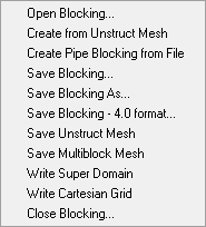
The blocking file (*.blk) includes details of the underlying framework used to create a structured hexahedral mesh in your project. Blocking files may also be loaded from or saved to unstructured mesh. The options for managing the blocking file are shown in Figure 11: Blocking Options.
- Open Blocking
To load a blocking file into your project and display its image, use the option.
Select the desired blocking file from the Open dialog box. You may have to browse to different working directory.
If a blocking file is already loaded in the project, the Blocking Exists window will open, prompting you to either merge the new blocking with the existing blocking or replace the existing blocking (similar to Figure 7: Geometry Exists Window).
- Create from Unstruct mesh
To create a hexa blocking file from an unstructured mesh composed entirely of hexa elements, select the option. This option is useful to regenerate a blocking file from a hexa mesh that was originally created from a blocking file, and is most robust when used in this fashion. This option can also be used on unstructured meshes originally written from external Multiblock formats such as Plot3D.
Note: Allowed element types are NODE, LINE_2, QUAD_4, and HEXA_8. Element types TRI_3 and PENTA_6 will be ignored. All other element types will cause an error.
It is also useful to create complicated 2D blocking by first creating 2D elements. Each quad element becomes a 2D hexa block. Complicated block structures can be made this way, which may not be possible to do in a top-down method.
- Create Pipe Blocking from File
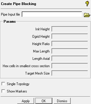
To create pipe geometry and blocking from a text-based input file, select the option. After selecting a properly structured Pipe Input file, click to generate the pipe geometry and blocking.
- Pipe Input file
Opens a dialog box to select your pipe data input file.
The input file can be created in a text editor or spreadsheet application. See Pipe Input file Structure for file specifications.
- Init Height
displays the surface height for the walls of the pipe (part CYL_SURFS), found in the input file.
- Ogrid Height
displays the Offset for the Ogrid Inflation layer.
- Height Ratio
displays the surface height ratio and tetra height ratio for part CYL_SURFS.
- Max Length
displays the largest edge length for the hexa mesh.
- Length Axial
displays the surface height for the inlets & outlets of the pipe (part CAP_SURFS).
Note: Surface height ratio and tetra height ratio for part CAP_SURFS is always 1-1.
- Hex cells in smallest cross section
displays the number of hexa cells to span the smallest cross section.
- Target Mesh Size
displays the desired size for the hexa mesh cells.
Note:Hex cells in smallest cross section and Target Mesh Size must fit within other meshing parameters otherwise they will be ignored.
These two parameters will be used to calculate Init Height, Height Ratio, and Max Length if any of the three values are set <= 0.0.
- Single Topology
sets how the is shown in the Display Tree. If enabled, only the single, merged topology is shown. If disabled, in addition to the merged topology (which will be the one with the highest index number), you will see a topology for each segment.
- Show Markers
adds markers for all Points in the pipe input file.
Pipe Input file Structure
The pipe input file contains the following data:
param init_heightvalueparam ogrid_heightvalueparam height_ratiovalueparam max_lengthvalueparam l_axialvalueparam n_acrossvalueparam target_sizevaluepointpoint_ID x y z pipe_radius bend_radiusRepeated as necessary, where point_ID are applied sequentially, x y z are the coordinates, pipe_radius sets the pipe size at that point, and bend_radius sets the curvature if an elbow segment.
pipepoint_ID point_IDRepeated as necessary, where point_IDs are the start and end Points of the individual pipe segments.
For example, the simple input file listing will create the simple pipe structure.
Figure 13: Create Pipe Example
param init_height
                                                  0.85
param ogrid_height 0.5param height_ratio 1.1param max_length 0.5param l_axial 0param n_across 17param target_size 333.0point 1 90 0 38 4.0 1.0point 2 90 20 38 4.0 1.0point 3 75 20 38 4.0 1.0pipe 1 2pipe 2 3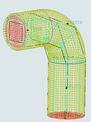
- Save Blocking
To update your
.blkfile with all your recent blocking work, select the option.If an existing blocking file,
filename.blkis already open, then this option will rename the existing blocking file tofilename.blk0(and then sequentiallyfilename.blk1,filename.blk2, etc.) and save the current file tofilename.blk.Note: The automatic indexing of blocking file names makes it easy to jump back to an earlier step if you wish.
Note: A key strength of Ansys ICEM CFD Hexa is the separate blocking layer file. This blocking file sit on top of the geometry (
*.tinfile) and is associated with it, but can be loaded with other topologically similar models and associated with them. In this way a blocking structure can be used with a family of geometries to rapidly create a series of high quality meshes or shared between colleagues working on similar tasks.- Save Blocking As
To create a new
.blkfile with existing blocking data, select the option.The Save as window prompts you for a File name and location.
- Save Blocking as 4.0 Format
To save the blocking file in the legacy Ansys ICEM CFD 4.0 format, select the option.
- Save Unstruct Mesh
To save the existing blocking pre-mesh in an unstructured hexa mesh format (
*.unsfile), select the option.The Save Mesh as dialog box prompts you for a File name and location. The unstructured mesh is not loaded.
- Save Multiblock Mesh
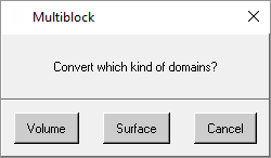
To save the current blocking data in the Multiblock structured format, select the option.
A dialog box will open prompting you to choose which type of domains to convert.
- Write Super Domain
To save the current blocking data in a merged, one-domain Multiblock mesh, select the option. The intended solver must be compatible with the Super Domain format.
- Write Cartesian Grid
To save the current blocking data in a Cartesian grid format, select the option. This is useful as a starting point for the Body-Fitted Cartesian (BFCart) meshing module (see the Cartesian file information on the Body-Fitted Mesh Method page).
To use this option, start by creating a block from the geometry extents. You can modify the vertex locations, but ensure the block remains aligned with a Cartesian coordinate system (right angled corners). Control the Cartesian grid distribution and biasing with splits and edge parameters. Also, edge distributions should be "copied to parallel" to maintain a consistent Cartesian distribution throughout the grid.
- Close Blocking
To remove the blocking information from the graphical display and close the loaded blocking file, select the Blocking > Close Blocking option.
If the blocking has been modified, the Save Blocking window will open, asking if you want to save the modified blocking (similar to Figure 8: Save Geometry Window).