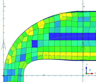
This option creates unstructured hexa mesh based on Cartesian mesh and fits it to the geometry. This works for both CAD and STL geometries. The mesher can handle "dirty" geometries as long as the Max element size is larger than the gap size.
Note: The max element size should be smaller than the thickness of the model.
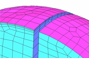
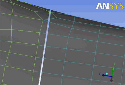
Figure 303: Handling of Gaps in the Geometry shows an example where the gap in the geometry is ignored by the body-fitted mesh method.
- Volume Part Name
allows you to select from the list of existing volume parts, select a part from the screen, or supply a new name. The inherited option will use the material points in the geometry to determine the part name for each region. The created mesh will be assigned to this part name.
- Enforce Split
These options allow you to use a pre-existing Cartesian mesh as the basis for the body-fitted Cartesian algorithm. This Cartesian mesh can be created elsewhere or can be created from Ansys ICEM CFD Hexa Blocking. It can include biasing and various aspect ratios. It can also be aligned with various features of the geometry.
- None
does not enforce a pre-existing Cartesian mesh, but rather creates a Cartesian mesh within the BFCart algorithm. This background mesh may have a given aspect ratio and may be aligned with the LCS. These options are controlled by the Global Mesh Parameters for BFCart.
Figure 304: BFCart Mesh Generated Using the None Option shows an example where this option has been used.
- Initial
In order to body fit, the BFCart algorithm must take the inverse of the Cartesian mesh. The end result of the process is that the nodes of the original Cartesian mesh become the centers of the resulting mesh. The split lines of the original mesh end up between the split lines of the final mesh.
Figure 305: BFCart Mesh Generated Using the Initial Option shows an example where this option has been used.
- Final
With the Final option, the supplied Cartesian mesh is inverted before the rest of the process begins so that the later body fitting inversion changes it back and the final grid can line up with the original. Due to internal complexities, this only works if the "uniform" Cartesian mesh is used. It does not work for 2 to 1 hanging node Cartesian mesh.
Figure 306: BFCart Mesh Generated Using the Final Option shows an example where this option has been used.
- Cartesian file
specifies the Cartesian grid file to be used when starting from an existing Cartesian grid file rather than generating one based on the mesh parameters of the current model. When used in conjunction with the option to export a block file as a Cartesian grid, you will be able to use block splits and edge parameters to control Cartesian bunching, distribution and aspect ratio. The imported mesh is used as the starting point before body fitting takes place.
- Key-Points
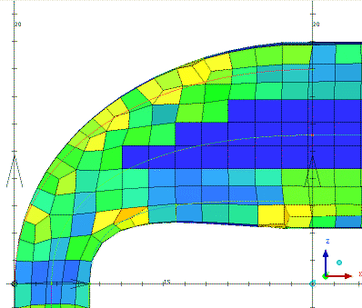
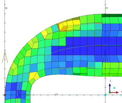
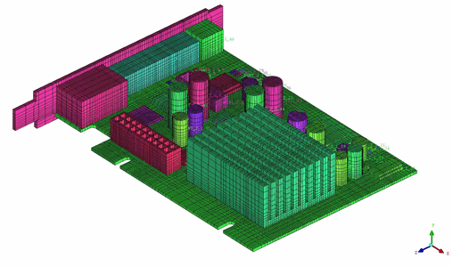
The Key-Points option can be used to align the body-fitted Cartesian mesh with corner points. Behind the scenes, this uses Key-Point blocking to create a Cartesian file aligned with the points and then uses the Final option with that file to align the Cartesian splits with the points. This option is useful for models having features aligned in Cartesian directions. An example of a circuit board is shown in Figure 307: BFCart Mesh Generated Using Key-Points with several features aligned in the Cartesian directions.
- Tolerance
specifies the minimum distance between adjacent grid lines. The default value is 0.0. If the default value is used, the tolerance will be computed internally based on the minimum entity dimension.
- Inflation
contains options for growing the body fitting inflation layer.
- Defined
grows the inflation layer on the parts for which the prism option is enabled in the Part Mesh Setup dialog. The setting works as an on/off toggle. The other Part Mesh Setup options for prisms, including initial "height", "ratio" and number of layers ("width"), are not yet used for BFCart inflation.
- All
grows the inflation layer on all parts.
- None
does not grow the inflation layer regardless of the settings in the Part Mesh Setup dialog.
Figure 308: Selective Inflation for the Body-Fitted Cartesian Mesh shows the inflation options available for the Body-Fitted Cartesian mesh generated for a sphere with a gap.
Figure 308: Selective Inflation for the Body-Fitted Cartesian Mesh
(A) Inflate Parts set to None — The mesh quality is poor as the stair step mesh is projected to the round surfaces of the sphere. 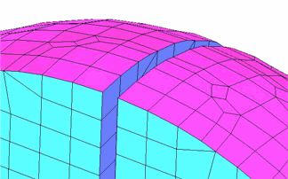
(B) Inflate Parts set to All — All parts are inflated, including the flat surface in the gap. The mesh quality is not as good as it could be due to miter elements generated in some corners. 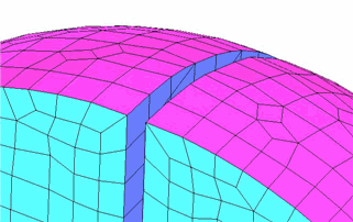
(C) Inflate Parts set to Defined — Only the sphere surfaces are inflated, while the gap surface part is not inflated. The inflation from the curved walls runs into the gap and gives the best resulting quality. On the left of the gap, the inflated hexas are split propagated to give better boundary resolution. 