


The Body-Fitted option creates unstructured hexa mesh of uniform size based on Cartesian mesh and fits it to the geometry. This works for both CAD and STL geometries. The mesher can handle "dirty" geometries as long as the cell size is larger than the gap size.
Note: The cell size should be smaller than the thickness of the model.
- Projection Factor
controls the tightness of the body-fitted Cartesian mesh to the geometry. Values can range from 0 to 1.0, where a value of 0 indicates Cartesian mesh totally free from the geometry, and a value of 1.0 indicates mesh that is strictly on the geometry.
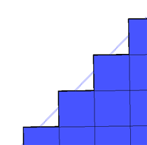
If the Projection Factor is set to 0, the resulting Cartesian mesh will have high quality hexa elements that transition via stairstepping (see Figure 259: Body-Fitted Cartesian Mesh With Projection Factor = 0).
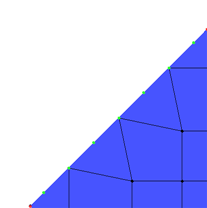
If the Projection Factor is set to 1, every node will be on the geometry surface (see Figure 260: Body-Fitted Cartesian Mesh With Projection Factor = 1). However, there may be hexa elements where two faces are planar.
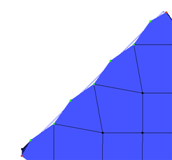
A Projection Factor of 0.9 will result in a mesh that deviates slightly from the surface so that the element quality is not as bad (see Figure 261: Body-Fitted Cartesian Mesh With Projection Factor = 0.9). The mesh is wavy as a result of this trade-off between capturing the geometry and obtaining a reasonable quality mesh.
- Split Degenerate
splits boundary quad and hexa elements with flat corners (triangular shaped), and propagates this split to produce higher quality elements. This option does not introduce pyramids or tetra elements.
Note: The shorter edge length introduced by this option may pose a problem for some users such as reducing the time step for explicit solvers. Also, the quality improvement is usually not as good as the improvement produced by the Create Pyramids option. You should try different options to determine which produces the best result for a particular topology and for a particular solver/physics.
Figure 262: Body-Fitted Cartesian Mesh with Boundary Hexa Elements shows the BFC mesh having boundary hexa elements with flat corners.
Figure 263: Split Degenerate Option shows the results of using the Split Degenerate option. The boundary hexa element has been split and the split is propagated through the neighboring elements.
For this model, the use of an inflation layer proves to provide the best quality, as shown in Figure 264: BFC Mesh with Inflation Layer.
- Create Pyramids
remeshes bad quality hexa elements (with determinant quality less than 0.05) using a Delaunay algorithm. This effectively replaces the poorest hexa elements with higher quality tetra and pyramid elements.
- Refinement Type
- Uniform
creates hexa elements of uniform size.
- 2-to-1
creates hexa elements of varying size with 2-to-1 size transition. This will introduce hanging nodes in the mesh.
- 3-to-1
creates hexa elements of varying size with 3-to-1 size transition. This mesh can be made conformal using the Edit Mesh > Resolve refinements option for limited configurations.
- Aspect Ratio
allows you to control the aspect ratio of the otherwise uniform Cartesian mesh. This can be used to fill the volume more efficiently in cases where there is a strong gradient aligned with the coordinate system. The default setting is
1 1 1. Changing the aspect ratio allows you to stretch the Cartesian grid. For example, setting the aspect ratio to1 2 0.75will result in a Cartesian mesh that is twice as long in the Y direction as the X direction and 0.75 times the size in the Z direction. This is applied to the entire model.You can also create a Cartesian file with varying aspect ratio. Use the Hexa blocking tools to create a block with splits and edge parameters to control the distribution. Then, use the option to convert the blocking to a Cartesian grid file. You can then refer to this file when computing the grid (see the Cartesian file option for details).
Figure 265: Hexa Mesh With Varying Aspect Ratio shows the Cartesian mesh for a Femur, with the aspect ratio varying along the shaft.
- Project Inflated Faces
allows full projection to the surface for inflated faces rather than limiting the projection with the projection factor.
- Outer Bounding Box
allows you to specify the outer mesh region for external flow meshes by setting the min-max coordinates of the flow region. This can be used instead of explicitly creating the tunnel geometry.
- min-max Coordinates
specify the explicit coordinates or click the selection icon to pick diagonal min and max coordinates to specify the outer bounding box size.
- Use active local coordinate system
allows you to orient the mesh along the active local coordinate system instead of along the global coordinate system. LCS are translated to equivalent Cartesian coordinates.
Boundary Layers
The Body-Fitted Cartesian mesher can create a layer of hexa elements parallel to the wall. These are necessary for properly capturing curvature and can be subdivided to get boundary layers. For some geometry parts, such as inlets, outlets and "flat" sides, you may not want to have this offset. However, you may want to apply inflation to flat parts if they are not in the Cartesian planes (X Y Z) to prevent stair-stepping. To determine if a part will have a single offset layer (with uniform aspect ratio), enable prism for the appropriate parts in the Part Mesh Setup dialog. For Ansys ICEM CFD, standard prism controls do not apply for Body-Fitted Cartesian meshing. Instead, if the prism option is enabled for a specific part, and then meshed using the Cartesian Body-Fitted method, the boundary layer will be offset. The boundary layer is determined on a part by part basis, so parts must be created and surfaces assigned appropriately.

In Figure 266: Example of Boundary Layers in Body-Fitted Cartesian Mesh, the prism option is enabled for the SURFS part containing the walls of the corner pipe but disabled for the INLET and OUTLET parts. When the Body-Fitted Cartesian mesh is computed, the boundary layer is grown along the SURFS part to better capture curvature, but terminates at the INLET and OUTLET. This single boundary layer can then be split to increase near wall resolution if needed.
Define Thin Cuts
The Define thin cuts option allows you to prevent elements stretching across a gap. You can define the thin cut pair using the button in the Tetra/Mixed Meshing parameters for the Robust (Octree) mesh method (see the Define thin cuts option).
Note: The thin cuts option works best for regions of the mesh which will be cut away, rather than thin solid regions where the mesh is to be retained.