The Robust (Octree) option will generate a tetra mesh using a top-down meshing approach. An Octree mesher does not require an existing surface mesh because one is created by the Octree process. It will accept a variety of parameters in a more general way. For instance, curve sizes are respected, but specific curve node spacing distributions are not. For a better understanding of the Octree meshing methodology, see The Octree Mesh Method in the Ansys ICEM CFD User's Manual.
- Run as batch process
allows you to run the meshing operation in batch mode.
- Fast transition
enables a faster transition from the more refined elements to coarser elements instead of a more gradual transition when computing the mesh. This will reduce the number of elements in the overall mesh. This option is particularly useful if you plan to delete the Octree volume mesh anyway since it saves time and memory during mesh generation.
- Edge criterion
determines to what extent a tetra is cut to represent geometry. The entered value is a factor of the tetra edge. After subdivision, if a tetra edge intersects an entity (surface), the tetra will be cut if the subdivision of the edge from the intersection is less than the prescribed value.
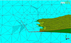
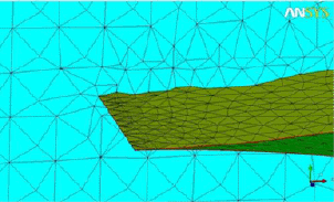
The values can range from 0 to 1. A larger value (above 0.5) may be prescribed if you want to ignore inexact duplicates, however geometry may not be properly captured if the value is too large. Increasing the value will increase the nodes moving to fit to the geometry. Reducing the value will increase refinement near entities, and will also reduce non-manifold vertices in trailing edges. The default of 0.2 is adequate for most cases. This value is useful in cases where thin cuts fail or are difficult to setup.
- Define thin cuts
allows you to resolve gaps based on pairs of surface or curve parts which are close to each other. The thin cut definition prevents surface elements from spanning between nodes on the two parts specified. This helps prevent non-manifold nodes in areas where the mesh size may be larger than the gap.
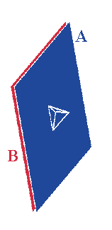
Figure 255: Thin Cuts shows an example of thin cuts. If the face of a tetra element has a surface/line/node on part A, then it cannot have a surface/line/node in part B.
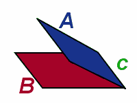
Note: If the surfaces of the two parts, A and B, meet (see Figure 256: Thin Cuts for Intersecting Parts), then the contact curve must be in a third part, C, or the thin cut will fail.
Clicking the button will bring up the Thin cuts window where pairs of parts can be selected or entered to define a thin cut "pair". A part can belong to more than one thin cut pair.
The following limitations apply to the definition of thin cuts:
If two surfaces approach asymptotically, the thin cut definition may eventually fail.
If the separation rule of thin cuts is violated at any point, all thin cuts will fail and be deactivated.
Due to the existing limitations with defining thin cuts, in some cases, it may be more effective to adjust the edge criterion.
- Edit entry
allows you to enter or edit the names of the parts in a pair.
- Select
allows you to select parts from a window displaying all the part names. The pair of parts selected should not be touching. If two surface parts meet along an edge (such as a sharp cusp) the curves and points between the parts must be in a third part name.
- Add
adds the thin cut pair selected or entered.
- Modify
allows you to modify a thin cut pair.
- Delete
allows you to delete a thin cut pair definition.
- Done
saves the thin cut pair definitions and closes the window.
- Cancel
cancels the thin cut pair definitions.
- Smooth mesh
when enabled, the mesh is smoothed after finishing subdivision down to the specified mesh sizes.
- Iterations
number of iterations to be performed for the smoothing to match the supplied Min quality.
- Min Quality
all elements with quality less than the specified value will be smoothed. The default is 0.4.
- Coarsen mesh
is a useful option if the geometry to be captured is difficult to mesh with the desired coarse mesh size. This allows the Octree process to fit to the geometry and flood fill with a finer mesh and then automatically coarsen it. For instance, it could mesh to capture features with approximately 150k elements and then automatically coarsen down to 15k elements while still maintaining the features. For most situations, you should mesh without this option and coarsen the mesh with the Edit Mesh tools where there are more controls available.
- Iterations
number of iterations to be performed for the coarsening to meet the specified Worst Aspect Ratio.
- Worst Aspect Ratio
a limiting factor for mesh coarsening (any elements below this quality will be excluded from the next iteration of coarsening).
- Fix Non-manifold
if enabled, the mesher will do additional work to try to fix non-manifold elements. These are only a possible problem, depending on your model and solver. See here for a description of non-manifold elements. It is strongly recommended to leave this option on and that you check for non-manifold elements after the mesh is computed.
Note: You may still have non-manifold elements for several reasons. They may be representative of the true geometry, and acceptable to the solver and therefore not a problem. It is also possible that the meshing parameters may be too coarse to cope with the geometry; in which case you could reduce the mesh size and/or apply thin cuts and/or reduce the edge criterion to allow for subdivision within the thin space. If only a few non-manifold elements exist, you can repair them with mesh editing. Try splitting nodes or delete the non-manifold elements and remesh locally.
- Close Gaps
is used to close gaps in the surface mesh between different materials. If enabled, triangles will be created to fill these gaps.
- Fix Holes
if disabled, the mesher will not perform extra steps to try to close holes to form a watertight volume. If enabled, the mesher will perform extra steps to close holes with a clear solution. If the mesher detects leakage with an unclear solution, it will interactively prompt you for the solution.
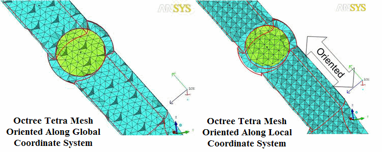
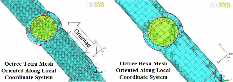
- Use active local coordinate system
allows you to orient the Octree mesh along the active local coordinate system instead of along the global coordinate system. If the LCS is not Cartesian, the equivalent Cartesian LCS is used.
Note: This option is helpful when converting oriented Octree tetra mesh to oriented hexa hybrid mesh (Convert Tetra to Hexa method – 12 tetra to 1 hexa).
In such cases, make sure the Use active coordinate system option is enabled for the 12 tetra to 1 hexa method in the Convert Tetra to Hexa DEZ (see the Convert Tetra to Hexa section).


