- Show All
Shows all parts in the display.
- Hide All
Hides all parts in the display.
- Reverse Blank All
Reverses which parts are blanked so that blanked parts become visible and visible parts are blanked.
Tip: If you have a large number of parts and want to blank most of them, it may be faster to select the parts you want visible, then use Blank Select followed by a Reverse Blank All.
- Expand All
Expands the entire Part Tree.
- Collapse All
Collapses the Part Tree.
- Blank Selected
Blanks all selected parts. A list of selected, blanked parts is displayed in the message window.
- Restrict Selected
Blanks all parts except selected ones.
- Delete Empty Parts
Deletes empty parts.
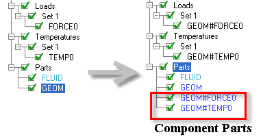
- Expose Component Parts
Exposes the hidden component parts created in Ansys ICEM CFD and makes them available in the Parts branch of the model tree.
Boundary conditions in Ansys ICEM CFD are assigned on a per part basis. When loads, constraints, pressures, forces, displacements, etc. are applied on individual entities, you usually don't want to see them as separate parts. So a hidden component part is created and the necessary boundary condition will be applied to the hidden part. This is usually preferable since it cuts down on clutter and these entities can be viewed or adjusted through the Loads or Displacements branches of the tree. Such hidden parts will be reported when you display the part information (right-click a part and select Info from the part display options).
For example:
------------------------------------------------------------------------------------
Info for part GEOM
------------------------------------------------------------------------------------
Geometry Info ----
Part contains 6 surfaces; Total surface area is 6.0
Part contains 12 curves
Part contains 8 points
Bounding box around part is {0 0 0} {1 1 1}
Part contains 2 hidden component part(s):
	GEOM:FORCE0 contains 1 surfaces
	GEOM:TEMP0 contains 1 surfaces
The ':' in the part name
GEOM:FORCE0indicates that the part is a hidden component of the partGEOM.However, for various reasons, some users may occasionally want to expose these hidden component parts as separate parts in the Parts branch of the model tree. This can be done with the Expose Component Parts option.
When the Expose Component Parts option is used, such parts will be renamed with a '#' replacing the ':' and they will be available in the Parts Tree.
Part GEOM:FORCE0 renamed to GEOM#FORCE0
Part GEOM:TEMP0 renamed to GEOM#TEMP0

2 part(s) renamed
Note: This operation cannot be undone.
Tip: CATIA V5 and other CAD tools use Component Parts for colors, etc. The hidden component parts are included in the Ansys ICEM CFD geometry file during conversion. You may find the Expose Component Parts option useful to expose the hidden color ID as a part name.
- Move Component Parts
This operation moves the component part into its parent. Unlike where component parts are renamed, the number of parts in the tree is not increased, resulting in reduced clutter. Following this operation, BCs on the hidden part are ignored. The operation is not reversible.
- Edit Attributes
Opens a table of the attributes of all the parts, as shown in the figure below. The part name, color, material, and thickness can be edited directly in the table.
The columns that are grayed out are not applicable for the type of geometry found in that part. Clicking the column heading will sort the data in ascending or descending order. Columns can be toggled on and off by right-clicking the headings and selecting the desired options. The column widths can be re-sized by moving the mouse over the column border and dragging it to the desired width. The vertical grab bar at the right of the table can be dragged aside to reveal the Display Window.
- Part Mesh Setup
Opens a table of the Part Mesh Setup options. This form is more efficient for large numbers of parts than the Mesh > Part Mesh Setup table.
The columns that are grayed out are not applicable for the type of geometry found in that part. Clicking on the column heading will sort the data in ascending or descending order. Columns can be toggled on and off by right-clicking on the headings and selecting the desired options. The column widths can be resized by moving the mouse over the column border and dragging it to the desired width. The vertical grab bar at the right of the table can be dragged aside to reveal the Display Window.
- "Good" Colors
Automatically selects new colors for all Parts, trying to pick ones that are easy to distinguish from the others in use. Normally, the colors are assigned by an algorithm that employs the parts name, which results in the same family in two different projects having identical colors. It is not, however, always possible to make all colors distinguishable from the others being used. The option provides an alternative.
- Color By Material
Assigns colors according to material instead of parts.
Individual Part Display Options
Right-click any part(s) in the Display tree to view the following display options:
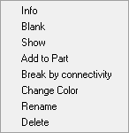
- Info
Reports information about the selected part(s) in the message window.
The reported information follows the same format and content rules as Show Parts Info, but it is specific to the selected part(s).
- Blank
Blanks the selected part in the display.
- Show
Shows the selected part in the display.
- Add to Part
Allows you to add entities to an existing part.
- Add to Part by Selection
Allows you to add geometry entities to the selected part. Click
 (Select entities) and select the entities to be added to the part.
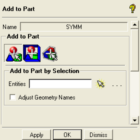
- Adjust Geometry Names
Adjusts the name(s) of the entities added to the part based on the original part selected. This option is disabled by default, implying that the original entity names will be retained.
- Add to Part by Region
Allows you to add mesh entities within the defined region to the selected part.
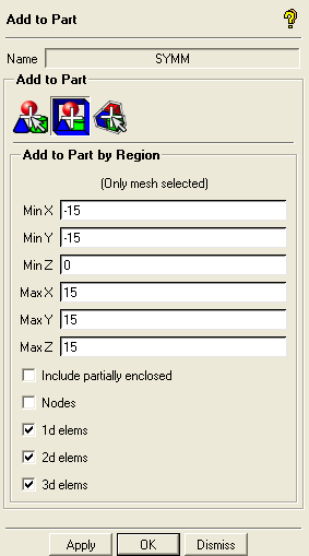
- Min X, Min Y, Min Z, Max X, Max Y, Max Z
Define the extents of the region.
- Include partially enclosed
Allows you to include elements that are partially enclosed by the defined region.
- Nodes
Allows you to add nodes within the defined region to the selected part.
- 1d elems
Allows you to add 1D elements within the defined region to the selected part.
- 2d elems
Allows you to add 2D elements within the defined region to the selected part.
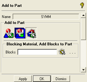
- Blocking Material, Add Blocks to Part
Allows you to add blocks to the selected part. Click
 (Select block(s)) and select the blocks to be added to the part.
- Break by connectivity
Creates a sub-part comprising all the surfaces along with attached mesh elements, from the selected part. This option is valid only for parts containing surfaces. The following additional options will be made available for the original part:
- Merge to part
Merges the sub-part comprising the surfaces with the original part.
- Create Sub-Assembly
Allows you to create a sub-assembly within the part from a list of selected parts. Selecting the Create Sub-Assembly option will open the Create Sub-Assembly DEZ (see Create Sub-Assembly for details).
- Change Color
Allows you to change the part color to one of your choice.
- Rename
Allows you to rename the part.
- Delete
Deletes the part.


