The Initialize Blocks option allows you to initialize blocks with the following options:
- 3D Bounding Box
allows you to create a 3D block enclosing the selected entities. If no entities are selected, the block will encompass the entire geometry.
Ansys ICEM CFD Hexa blocking is typically done in a top down method that starts from a single large block which is subdivided down to create the topology. Initializing this 3D bounding box is the first step.
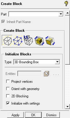
Note: Not selecting any entities is more efficient, particularly for scripting, if you intend to block the geometry extents.
- Project vertices
when enabled, the initial block vertices will be moved to the nearest locations on the geometry.
- Orient with geometry
attempts to find the best fit of the geometry in any orientation, and to create the smallest block possible around the geometry selected.
- 2D Blocking
enables the creation of a surface blocking composed of six 2D face blocks forming a box around the geometry.
- Initialize with settings
allows you to use the user-defined settings set in the Hexa/Mixed Meshing Options DEZ () and saved under
.aienv_optionsfor block initialization. For example, you can set the default bunching ratio to 1.2 and the multigrid level to 3 and save the settings. Future block initialization with the Initialize with settings option enabled will use these settings as default.This option is enabled by default.
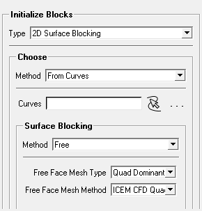
- 2D Surface Blocking
Creates 2D surface blocking based on input. This 2D surface blocking can be used to create a shell mesh, or as a precursor to the 2D to 3D operation to create 3D MultiZone blocks or to extrude/rotate the 2D blocks into 3D blocks.
When Inherit Part Name is enabled, the part name will be inherited from the underlying surface parts.
Note: If surface mesh sizes (max size, height, and height ratio) have been previously set, they will be used to calculate the distributions for the blocking edges.
2D Surface Blocking can be initialized from either Surface or Curve geometry:
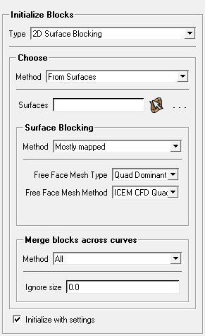
- From Surfaces
Select specific surfaces for initializing 2D surface blocking. If none are selected, all surfaces will be initialized. In general, a 2D block is created for each surface, but some sliver faces may be skipped if they are smaller than the ignore size, or faces may be skipped if using options for Merge blocks across curves.
Note: Geometry topology information is required to establish connectivity between the blocks. You can check topology by right-clicking on Curves in the model tree and enabling the Color by Count option. Make sure that you have double edges (red curves) between surfaces that you want connected. Single edges (yellow curves) may indicate a gap between surfaces. Build diagnostic topology if necessary.
- From Curves
Select specific curves for initializing free 2D surface blocking. One 2D surface block is created from the selected set of curves.
This option may be useful to build an intricate surface blocking from multiple simpler profiles, with the ultimate intent of extruding the 2D blocking.
Tip: This process expects the curves to be approximately planar. For severely non-planar curves, use as the .
- Surface Blocking
Whether initialized from Surfaces or from Curves, set the Surface Blocking Method, Free Face Mesh Type, and Free Face Mesh Method.
- Method
specifies the surface blocking method. The following options are available:
Note: Blocks can be converted between free and mapped blocks using Edit Block > Convert Block Type.
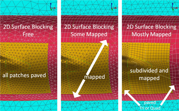
- Free
creates all free (unstructured) 2D blocks. Unstructured blocks can have any number of sides, and have a different number of nodes on opposite sides, with a resulting nonuniform element pattern. The mesh inside free blocks is paved (recursive loop algorithm) and can be all quad, quad dominant, quad with one tri, or all tri.
Note: The default mesh type that will be used is defined under Settings > Meshing > Hexa/Mixed > Unstruct face mesh type. You can override the default setting by changing the mesh type in the Free Mesh Type list. After the 2D Surface Blocking is generated, you can modify the mesh type for any particular Free block using the option.
- Some mapped
maps surface patches with 4 corners (possibly more sides). A mapped surface has matching numbers of nodes on opposite sides. The mesh is "mapped" across to the opposite side of the block and is always quad surfaced mesh. Remaining surfaces with more or less than 4 corners are blocked with "free" blocks as above.
- Mostly mapped
tries to subdivide surface patches with more or less than 4 corners into mappable patches. For instance, a 3 cornered surface is divided into a quarter Ogrid (Y-Block) pattern. A half circle is divided into a half Ogrid (C-Block) pattern, other arbitrary shapes are simply divided. Other surface patches with 4 corners are also mapped. Any remaining patches or sections of patches which still cannot be mapped (more or less than 4 corners) are blocked with "free" blocks as above.
Figure 312: Surface Blocking Methods shows the Free, Some mapped, and Mostly mapped surface blocking methods.
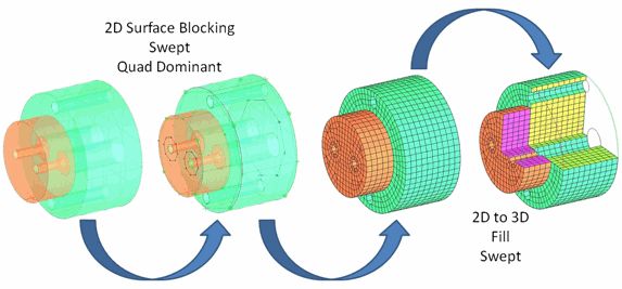
- Swept
creates surface blocks in preparation for the operation. Sides of sweepable bodies are mapped, sources are free or mapped and copied to the targets. This method can handle multiple sources and targets.
- Swept Surfaces
This option is available only for the Swept Method. Select all the source and target surfaces (multiple sources and targets are supported). If it is easier, select all surfaces involved (sources, targets, sides). If you intend to sweep everything, do not select surfaces at all and everything will be selected.
Figure 313: Surface Blocking-Swept shows the swept surface blocking. In this case, geometry topology was built between the two parts so that the sweep could pass through both parts.
Note: The 2D Surface blocking is automatically imprinted to deal with multiple source and target situations.
Note: As with all the 2D surface blocking methods, geometry connectivity translates into blocking connectivity, so make sure to check topology.
- Free Face Mesh Type
specifies the type of mesh for the free blocks. The following options are available:
All Tri
All Quad
Quad Dominant
Quad w/one Tri
- Free Face Mesh Method
specifies the process for meshing free faces. The following options are available:
ICEM CFD Quad - method is based on a recursive loop-splitting algorithm.
Gambit Pave - method is based on the Gambit paving advancing front algorithm.
Auto - method lets the program determine the method based on size and curvature.
- Merge blocks across curves
By default, surface patches are defined by each surface. However, surfaces can be combined to improve the blocking or prevent slivers. This is controlled or limited by dormant curves or the Ignore size tolerance.
Behind the scenes, a "loop" is formed around the perimeter of each surface. If two blocks are merged across a curve, the loops on either side are simply replaced by a loop that includes the perimeters of the 2 surfaces combined. The geometry (curves and surfaces) is unaffected by the operation.
- Method
- All
will merge a sliver surface with its larger neighbor if the characteristic edge length is less than the tolerance.
- Respect non-dormant
will not merge if the curve between the surfaces is not dormant. This does not mean it will force a merge if the curve is dormant. Tolerance still determines the merge.
- None
will not merge based on tolerance.
- Merge dormant
will merge across dormant curves regardless of tolerance.
Note: To make a curve dormant, delete without the Delete Permanently option. The > option will also make curves dormant based on a feature angle. To restore a dormant curve, use the > option. To view dormant curves, right-click Curves in the model tree and enable Show Dormant.
Note: After creating the 2D blocking, the option can be used to achieve a similar result.
- Ignore size
specifies the tolerance that Merge blocks across curves uses to determine whether to merge sliver blocks to the adjacent block. The sliver block's distance across the thin edge must be smaller than this value for the block to be merged to the adjacent block.
Note: These parameters apply only when method is selected.
- Initialize with settings
allows you to use the user-defined settings set in the Hexa/Mixed Meshing Options DEZ () and saved under
.aienv_optionsfor block initialization. For details, refer to Initialize with settings described above.Note: These parameters apply only when method is selected.
- 2D Planar
allows you to create a 2D Planar block in the XY plane fitting around the entire geometry. 2D planar blocking is intended to work in the XY plane, and moving it to another orientation will make it difficult to position internal vertices. It is better to rotate your geometry to the XY plane where Z=0.
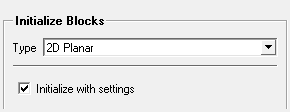
- Initialize with settings
allows you to use the user-defined settings set in the Hexa/Mixed Meshing Options DEZ () and saved under
.aienv_optionsfor block initialization. For details, refer to Initialize with settings described above.
- 3D Multizone
An automated method to create 3D blocking using the sequential operations of 2D Surface Blocking followed by 3D Fill. The volume is decomposed into a combination of mapped, swept and free blocks. Source imprint surfaces and Mapped/Swept Decomposition options affect how the volume is decomposed and can aid with sweeping, etc.
Important: MultiZone requires body information to run.
If importing geometry using Import Model, the body information already exists. Use > > to visualize the material point(s) in the bodies. See By Topology.
If a geometry was created in ICEM CFD or imported using another option, you should ensure that the topology information is complete (see Build Topology). You can create the material point(s) using > , and select either or . See Create Body.
When creating 3D MultiZone blocking on models with multiple bodies, the blocks of the different bodies will be put into different Parts, starting with the Part name defined (default is CREATED_MATERIAL_1), and incremented for each body.
Note: If your geometry contains an internal surface, perform the following steps before initializing the blocking:
Create a new Part containing only the internal surface.
Set the new part as an Internal wall in the Part Mesh Setup dialog box.
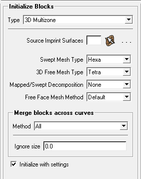
- Source Imprint Surfaces
Select faces to be used to imprint feature edges in the initial 2D surface blocking.
In the MultiZone decomposition process, the source faces define the path for sweeping, leaving the other faces to be treated as side faces. Then, in trying to create as many swept blocks as possible, the software tries harder to make non-source faces mapped and source faces free. All source faces must be properly matched with other source faces. If source faces cannot be properly paired, the software will not be able to create as many swept or mapped blocks, resulting in free block(s).
- Swept Mesh Type
Select the shape of elements supported in the structured regions.
- Hexa
(Default). Supports an all hexahedral mesh, extruded from quad surface elements, for the 3D fill mesh.
- Hexa/Prism
Supports a hexahedral dominant mesh, with prisms extruded from quad and triangle surface elements, for the 3D fill mesh.
- Prism
Supports a prism mesh, with prisms extruded from triangular surface elements, for the 3D fill mesh.
- 3D Free Mesh Type
Select the shape of elements supported in unstructured regions when it is not possible to generate a pure hex or hex/prism mesh without slicing.
- Tetra
Regions of the model that cannot be blocked to support a mapped mesh will be filled with tetrahedral elements extruded from all triangular faces.
- Tetra/Pyramid
Regions of the model that cannot be blocked to support a mapped mesh will be filled with tetrahedral elements in the core, transitioning to pyramid elements, extruded from quad faces at the surface.
- Hexa Dominant
Regions of the model that cannot be blocked to support a mapped mesh will be filled primarily with hexahedral elements, transitioning to pyramids and tets as needed.
- Hexa Core
Regions of the model that cannot be blocked to support a mapped mesh will be filled primarily with an array of hexahedral elements aligned to the Cartesian coordinate system. This is connected to the remainder of the free prism/tetra hybrid mesh by automatic creation of pyramids.
Hexa Core allows for a reduction in the number of elements for quicker solver run time and better convergence.
- Mapped/Swept Decomposition
Select a strategy for how to decompose the volume into mapped, swept and free blocks.
- None
Decomposition is not allowed, resulting in one free 3D block with all faces also being free.
- Standard
(Default) Software tries to create mapped, then swept, then free blocks as possible. For models that are sweepable, all blocks that are created should be mapped and/or swept. Selecting source imprint surfaces may be necessary for these cases. For models where the decomposition is not straight-forward, free blocks with a combination of free and mapped faces will be created.
- Aggressive
Very similar to Standard, but the software tries to generate more mapped faces in the process. For some cases this could help create more mapped or swept blocks. In other cases it may not help with the decomposition, but may result in more mapped faces attached to free blocks.
- Free Face Mesh Method
Select the method for generating the 2D mesh on surfaces and areas that are free meshed.
- Default
Automatically uses a combination of Uniform and Pave mesh methods depending on the mesh sizes set and face properties.
- Uniform
Uses a recursive loop-splitting method to create a highly uniform surface mesh.
This is a good option when all edges have the same sizing and the faces being meshed do not have a high degree of curvature. The resulting mesh orthogonality is generally very good.
- Pave
This is a more reliable method to create an all-quad mesh on faces with high curvature, and also when neighboring edges have a high aspect ratio.
- Merge blocks across curves
By default, surface patches are defined by each surface. However, surfaces can be combined to improve the blocking or prevent slivers. This is controlled or limited by dormant curves or the Ignore size tolerance.
Behind the scenes, a "loop" is formed around the perimeter of each surface. If two blocks are merged across a curve, the loops on either side are simply replaced by a loop that includes the perimeters of the 2 surfaces combined. The geometry (curves and surfaces) is unaffected by the operation.
- Method
- All
will merge a sliver surface with its larger neighbor if the characteristic edge length is less than the tolerance.
- Respect non-dormant
will not merge if the curve between the surfaces is not dormant. This does not mean it will force a merge if the curve is dormant. Tolerance still determines the merge.
- None
will not merge based on tolerance.
- Merge dormant
will merge across dormant curves regardless of tolerance.
Note: To make a curve dormant, delete without the Delete Permanently option. The > option will also make curves dormant based on a feature angle. To restore a dormant curve, use the > option. To view dormant curves, right-click Curves in the model tree and enable Show Dormant.
- Ignore size
specifies the tolerance that Merge blocks across curves uses to determine whether to merge sliver blocks to the adjacent block. The sliver block's distance across the thin edge must be smaller than this value for the block to be merged to the adjacent block.
- Initialize with settings
allows you to use the user-defined settings set in the Hexa/Mixed Meshing Options DEZ () and saved under
.aienv_optionsfor block initialization. For details, refer to Initialize with settings described above.