 The Build Topology option creates a series of curves and points from surface edges and corners depending on the proximity of the surface edges to each other. If the curves are within a geometric tolerance, they are merged together as one. The curves are then displayed in a specific color to illustrate their connectivity in the surface data, which can be used to determine any gaps or holes in the geometry.
Note: Dormant Entities
Curves and points can be made dormant either by deleting them with the Delete permanently option disabled, through building topology with feature angle and filter points/curves enabled, or through feature detection tools. If a curve or point is dormant, it will not be recreated when building topology, but build topology may make it active. If a curve or point is permanently deleted, it is removed from the database. If the topology is rebuilt, the curve will be recreated. Flood fill, and patch based meshing will also fail across a boundary (curve or point) that has been permanently deleted. Curves and points that are unattached to surfaces or curves will always be permanently deleted, as the sole purpose of dormant curves and points is to maintain connectivity between attached geometry.
Note: Embedded Entities
Points that are within the build topology tolerance from a surface, and curves that are parallel to a surface within the build topology tolerance and not on the boundary of the surface will be embedded into the surface. If a point or curve is embedded or linked to the surface it means that the surface has connectivity to these curves and points. The patch dependent mesher requires this connectivity to include the curve/point as a boundary to the mesher. An embedded curve or point is different than a boundary curve or point in that it is doubly connected to the surface instead of having a single connection like a boundary entity. An embedded curve is connected to the surface twice (on positive and negative sides of the surface), whereas the boundary curves are only attached to the surface on one side.
If the embedded curve is attached to a second surface, the embedded curve becomes a multiple edge, and defines a T-connection. Typical T-connections connect 3 surfaces, but since in the case of an embedded curve the underlying surface is not fully trimmed, the doubly connected edge helps represent the geometry in a more accurate fashion. That is, the connection is defined to the positive and negative side of the base surface and to the boundary of the second surface.
Table 2: Build Topology Colors
|
Yellow |
Single or free edge curves (those adjacent to only one surface) |
|
Red |
Double edge curves (curves adjacent to two surface) |
|
Blue |
Multiple edge curves (curves adjacent to three or more surfaces) |
|
Green |
Unattached curves (not attached to any surface) |
Topology can be built with the following options.
- Tolerance
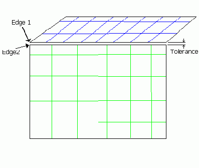
The tolerance is defined in units of the model, and controls how accurately you want to treat surface-to-surface proximity. The tolerance between two surfaces is shown in Figure 220: Tolerance.
For any two faces (surfaces) that meet at a common edge (curve), there is typically a finite distance between the two edges. By default, a curve is associated with all the edges of each face. In the figure above, a curve would be associated to edge 1, and a second curve would be associated to edge 2. This topology of the two surfaces would indicate a gap in the model.
Typically, Ansys ICEM CFD meshers can handle this if the gap is smaller than the proposed element size on the surfaces or curves. Therefore, you would set a tolerance larger than the gap if you are using a large element size. A tolerance smaller than the gap would create yellow curves which could be fixed.
The recommended tolerance is approximately 1/10th the size of the average mesh size.
- Filter by angle
Filtered curves are made dormant if the surfaces on either side meet at less than the specified angle. Filtered points are made dormant if the curves on either side meet at less than the specified angle. Feature curves and points that meet at greater than the specified angle remain. Since Octree Tetra forces the mesh to respect curves and points, removing unnecessary ones increases the patch independence and mesh quality. Points or curves (even double yellow curves) can also be deleted manually for the same purpose.
- Filter points
Enabling this option will filter points by the angle between their respective curves, as long as the angle is not zero.
- Filter curves
Enabling this option will filter curves by the angle between their respective surfaces, as long as the angle is not zero.
- Method
Topology can be built for All parts, Only visible parts, or by Selection of specific entities.
Note: The All parts option is different from choosing the Selection Method and then Select all appropriate objects (key = a), and will yield a different result. The All parts option includes dormant entities, but the Selection Method > Select all appropriate objects does not include dormant entities.
- Part by part
The topology is built part by part.
- Single curve cleanup
Enter a value for the Single Edge Tolerance. This option will merge single curves only that are within the Single Edge Tolerance distance of each other.
Note: This is useful for certain models with small features, where the Build Topology Tolerance must be kept smaller than those features. In such cases, larger gaps with single edges can be cleaned up with this option.
- Split surface at T-connections
Surfaces that form a T-connection will be split and trimmed at the common edge. When meshed, the mesh will conform to the common edge.
- Split facets at interior curves
Faceted surfaces are trimmed along interior curves that do not span the surface or form a closed loop. When meshed, the mesh will conform to the interior curve.
- Join edge curves
Combines edges with the defined angle to concatenate smaller curves into a single curve. This option applies to both Bspline and faceted data.
- Delete unattached curves and points
Deletes any green curves and unattached points. Sometimes you may keep these since they could be used as construction curves.
- Keep dormant as dormant
Entities that were made dormant by the user will be kept dormant when the topology is built.
- Keep old point names
Attempts to retain the existing point names when Build Topology is run, otherwise new names will be created. Default is on.
- Ignore Local Feature
This option allows Build Topology to disregard local tolerance, relative to edge length, and merge away features that are smaller than the global Build Topology tolerance. Default is Off.
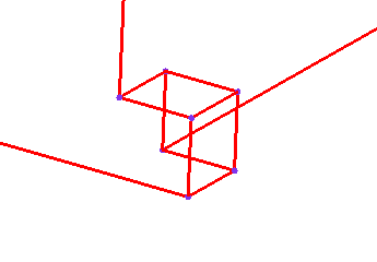
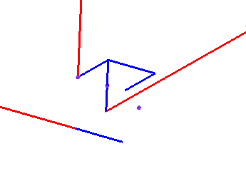
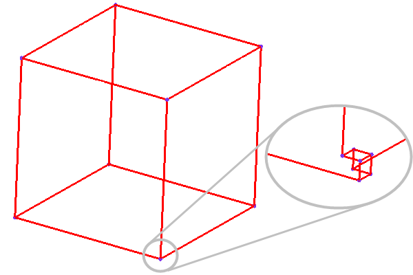
This option is useful if a model has a range of scales and retaining the small feature would cause high cell count or poor quality. The model shown in Figure 221: Model with Small Feature has a small feature which is highlighted.
If the global Build Topology tolerance is set to a value larger than the local feature size, the curves of the local feature may become degenerate and be collapsed when this option is enabled.
Figure 222: Use Local Tolerance Option
(A) Ignore Local Feature disabled (default) 
(B) Ignore Local Feature enabled 


