


Another option to set up a System Coupling simulation is to use the System Coupling Graphical User Interface (GUI). This section highlights the important steps and settings in typical System Coupling applications using Forte. In general, please follow this workflow:
Start the System Coupling GUI and select the working directory:
On Windows, you may start the GUI from the Start menu and select Ansys 2024 R2 > System Coupling 2024 R2. The System Coupling GUI opens and prompts you to navigate to your working directory.
You may also start the GUI using command line. Open a command line prompt (Windows) or a shell terminal (Linux) and navigate to your working directory.
Execute the following command:
Windows:
> "c:\Program Files\ANSYS Inc\v242\SystemCoupling\bin\systemcoupling" -G
Linux:
$ "$HOME/ansys_inc/v242/SystemCoupling/bin/systemcoupling" -G
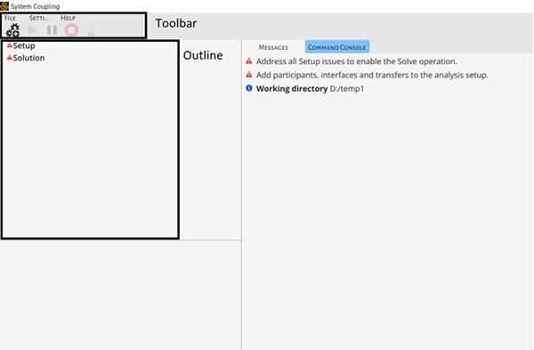
You will see the user interface shown as in Figure 9.5: System Coupling Graphical User Interface after it starts after it starts.
Add System Coupling participants:
You may click the Add a Participant button
 in the toolbar, or right-click
Setup and choose Add Participant
in the outline. The Add Participant dialog appears. Add
the participant using its Input File. Select the
Participant Type and choose the Input
File that has been prepared.
in the toolbar, or right-click
Setup and choose Add Participant
in the outline. The Add Participant dialog appears. Add
the participant using its Input File. Select the
Participant Type and choose the Input
File that has been prepared.To add the Forte participant, select the Participant Type as Forte and add the Forte project file (.ftsim) as the input. The program recognizes that Forte will be run in the folder containing the project file.
To add the other participant such as Fluent, select the Participant Type as Fluent and add its System Coupling Participant file (.scp) as the input. The program recognizes that Fluent will be run in the folder as specified in the .scp file.
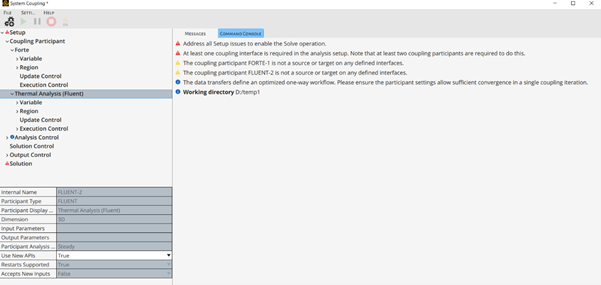
After the two participants are successfully added, you will see them listed in the outline, as shown in Figure 9.6: System Coupling Graphical User Interface after Participants are Added.
Add coupling interface(s) and data transfer:
Right-click Setup in the outline, and select Add Coupling Interface. You will see a "CouplingInterface1" under "Coupling Interface".
For this interface, specify which participant is Side One, and which participant is Side Two. For example, you may set Fluent as Side One, and select the name of the boundary from its Region List for the coupling interface. Then, set Forte as Side Two, and select the boundary name from its region list for the same coupling interface.
Then, set up the data transfer on the coupling interface. Right-click the interface and select Add Data Transfer. Here, you need to specify the Target Side of this data transfer. In this example, we choose Side One (Fluent) as the target. Then, specify the variable name for the data transfer. The names might look different for each participant, but you need to make sure that they refer to the same variable. For example, we can set the Source Variable as Heat_Rate and the Target Variable as heatflow.
In a System Coupling simulation, the data transfer is typically two-way. So, we need to add another data transfer with the Target Side set as Forte in this example. Set the Source Variable as temperature and the Target Variable as Temperature.
Note: The settings given here are meant to match the settings presented in the example in Step 4a: Create a System Coupling Python Run Script. You need to explore your own settings based on the applications to be simulated.
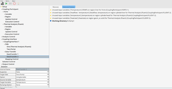
After you have successfully defined the coupling interface and the data transfers on it, you will see them listed in the outline, as shown in Figure 9.7: System Coupling Graphical User Interface after Coupling Interface is Defined.
Specify controls for the coupled simulation:
Review Analysis Control in the outline. The Analysis Type should tell you whether this is a Steady (for steady-state) or a Transient analysis.
Note: The Analysis Type is automatically determined based on the status of the participants. If one of the participants is a steady-state analysis, then the System Coupling's analysis type will be Steady. If all the participants are transient analyses, then the System Coupling's analysis type will be Transient.
Then, review the settings in Solution Control in the outline. In case of a Transient analysis, you must define the End Time of the simulation and the Time Step Size, which is the coupling step size.
For the differences between a steady-state and a transient System Coupling simulation, refer to Steady-State and Transient Coupled Analysis.
Once you have completed these important settings in the GUI, you are ready to start the System Coupling run. Proceed to How To Run System Coupling.
Tip: if you already have a Python script written ready to set up a System Coupling simulation, as detailed in Step 4a: Create a System Coupling Python Run Script, you could read it into the GUI by File > Run script. The simulation will be automatically set up without your going through the above steps manually. Make sure to remove the
Solve()command from the script if you do not wish to start the System Coupling simulation right away after the script is read.
For more detailed documentation of the System Coupling GUI, see Using System Coupling's Graphical User Interface (GUI) in the System Coupling User's Guide.