Note: Running this simulation is estimated to take 25 minutes on the Intel ® Xeon ® processor E5-2690 at 2.90 GHz (8 total cores).
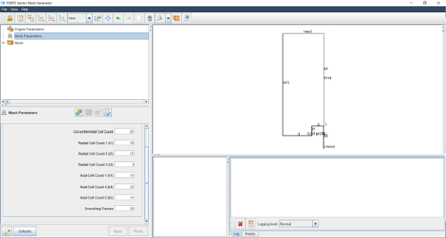
It is easy to create your own mesh instead of using the supplied mesh. Meshes can be created using the Ansys Forte Sector Mesh Generator, for periodic (sector) meshes, or the Automatic Mesh Generator for full 360° meshes. In this section, we describe the use of the Sector Mesh Generator Utility (shown in Figure 1.9: Sector Mesh Generator Utility after mesh is imported).
The Sector Mesh Generator provides six different sample mesh topologies for different piston bowl shapes. The shape of the bowl determines which mesh topology is most appropriate. The next steps accomplish the following:
The name of the bowl profile for this case is sandia_bowl_profile.csv, which is one of the files in the samples download. In the .csv file, the first column is the X-coordinate and the second column is the Z-coordinate. For this simple bowl geometry, there are only 3 profile points needed to define the profile and, for Topology 3, exactly 3 are required.
Note: For Ansys Forte sector-mesh simulations, the piston should always be oriented to move in the positive Z direction. Note also that the last profile point should be at X = 0.0.
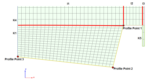
For this piston bowl, Topology 3 will be used, since it is a square-shaped bowl, as shown in Figure 1.10: Template for Topology #3 , below.
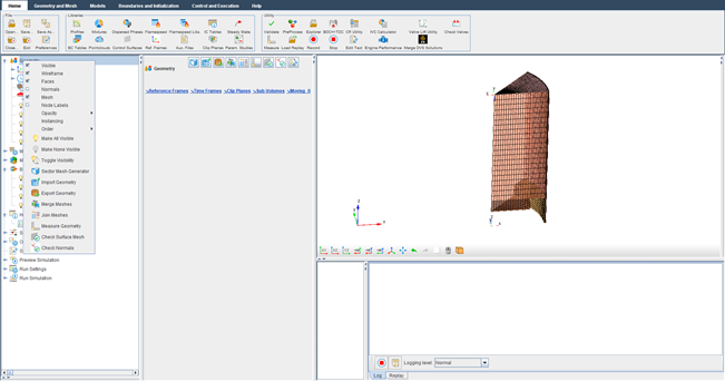
To create a sector mesh, go to the Workflow tree and click Geometry. This opens the Geometry icon bar. Click the Sector Mesh Generator
 icon to open the Sector Mesh Generator Utility (SMG).
Start by clicking the Engine Parameters node in the SMG Project tree to open an Editor panel.
In the Sector Mesh Generator’s Engine Parameters panel, the first step is to import the simple bowl profile that was provided with the sample. To do this, go to the Bowl Profile pull-down menu and select Create new... and click the Pencil
 icon. This opens the Profile Editor window.
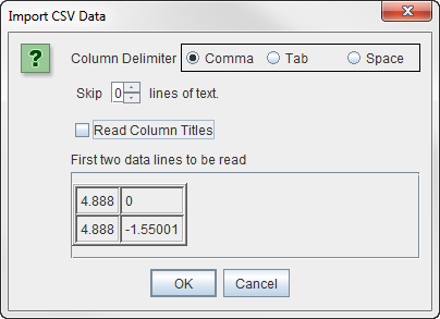
In the Profile Editor, click the Load CSV button (you may need to expand the window vertically to see the button below the table) and then browse to, select, and open the sandia_bowl_profile.csv file. In the dialog, select Comma as the Column Delimiter and uncheck the Read Column Titles box and click OK. See Figure 1.11: Import CSV dialog for creating a bowl profile .
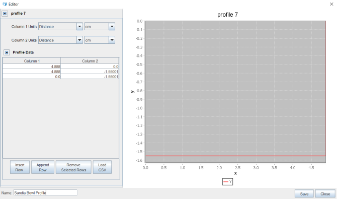
At the bottom of the Profile Editor Panel, in the text entry field under Profile Name, enter a name for the profile, such as "Sandia Bowl Profile". See Figure 1.12: Sector Mesh Generator Utility with new Profile and Editor panel . Click Save and click Close for the SMG window.
Select and expand the Include Crevice Block option and set Crevice Height = 3.72621 cm. Click Apply. A diagram of the engine geometry appears.
Now go to the Mesh Parameters node in the SMG Project tree. Select Topology 3 in the Topology pull-down menu. To see the topology template selected, click the Show Topology button. It should look like that shown in Figure 1.10: Template for Topology #3 above.
Enter the information indicated in the Topology #3 diagram, as follows:
Once all the settings are specified, click Apply. Review the diagram of the profile information in the Sector Mesh Generator’s 3-D View panel to verify that the settings make sense.
Click Generate a Mesh
 at the top of the Mesh Parameters Editor panel. Ansys Forte will
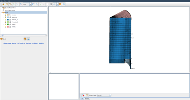
automatically generate the sector mesh. When it is finished, the resulting mesh will appear
for your review in the 3-D View window within the Sector Mesh Generator window, as shown in
Figure 1.13: Diesel sector sample case
.
at the top of the Mesh Parameters Editor panel. Ansys Forte will
automatically generate the sector mesh. When it is finished, the resulting mesh will appear
for your review in the 3-D View window within the Sector Mesh Generator window, as shown in
Figure 1.13: Diesel sector sample case
.For this exercise, click Mesh Parameters in the Sector Mesh Generator’s Project tree, then click the Import to Forte Project
 icon at the top of the SMG Editor panel. Now go to the Simulate window
and see the new Geometry items added to the Workflow tree. If you cannot see the mesh that you
just generated displayed in the main 3-D View panel, right-click on these Geometry items for
options to make their Mesh visible. To center and resize the mesh display, click the
Refit
icon at the top of the SMG Editor panel. Now go to the Simulate window
and see the new Geometry items added to the Workflow tree. If you cannot see the mesh that you
just generated displayed in the main 3-D View panel, right-click on these Geometry items for
options to make their Mesh visible. To center and resize the mesh display, click the
Refit  icon on the Ansys Forte toolbar.
Close the Sector Mesh Generator window.
Note: To see the mesh lines in the geometry, right-click Geometry in the Workflow tree (on the left-hand side) and turn on Mesh. You can modify settings here to refine or coarsen the mesh, for example, and regenerate, or you can open (import) the newly created mesh into the sample project into Ansys Forte. Alternatively, you can use the Save to File button to export to a mesh file that can later be imported into Ansys Forte.
Continue with Set Up the Case .