


The following section describes the options available to interact with your simulations, runs and results files from the Project View.
When a simulation is not yet loaded, the following options are available:
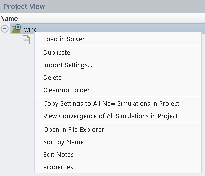
Loads the simulation. This will launch the solver session in the background. (See Loading a Simulation for more information).
Enables you to import settings from other simulations into the current simulation. Selecting this command will open a browser where you can navigate to and select a Fluent Aero run.settings file to import settings from. Any relevant settings from that file will be imported and used in the Outline View and Input: Design Point table of the current simulation. If the imported settings file contains items that are not relevant to the current simulation (including different boundary zones or custom input parameters that do not exist in the current simulation) these irrelevant settings will not be imported.
Deletes the simulation folder. This will remove the simulation from the Project View and delete all child files and folders from the disk.
Erases all simulation files such as cleanup-*, and serverinfo-*.
This command will copy the run.settings of the selected simulation to all other new simulations in the project that do not already contain results. This command can be useful to apply a standard group of settings to many simulations inside a project, without having to import settings to each one individually.
When selected, a Convergence window will appear where the convergence history of all the design points of all simulations in the project are displayed. The dataset will show the simulation name followed by the design point id (for example, Simulation01:DP-01) so that each convergence curve can be easily identified.
Opens the simulation directory in the file explorer of the local operating system.
Sorts all files in the simulation alphabetically by name. By default, the simulation files are initially sorted by time of creation.
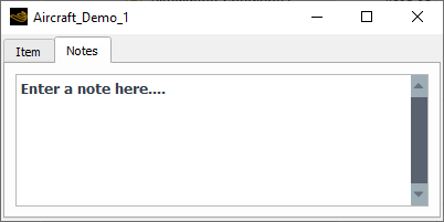
Opens a Properties window, showing the Notes panel, where you can add text notes to the selection. If a text note is added, the item inside the project view will be displayed with a * icon next to its name, signifying a note has been added.
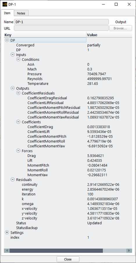
Opens a Properties window showing the Metadata and properties of a simulation. The figure below shows an example of the contents of a simulation Properties window.
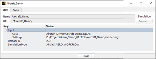
In the above figure,
The Name of the simulation and its URL path are shown at the top of the Item tab.
Input shows the input case file used in the simulation.
The Notes tab can be used to write any notes that you would like to add to better describe this simulation.
When a simulation is loaded, the following additional options are available:
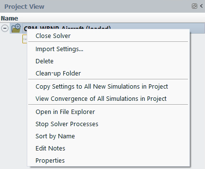
Closes the simulation and closes the background solver session if enabled.
Shows the Outline View window associated with the simulation, where the simulation settings can be investigated.
Launches the cleanup-fluent-* script file associated with the simulation, which will close the associated background solver session.
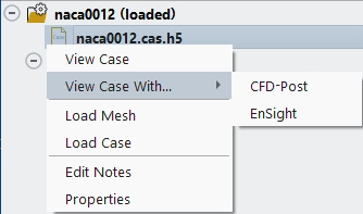
Opens the case for post processing using the Post-Analysis tool. A Post-Analysis node will appear in the Outline View and the selected case file will be loaded.
Opens a CFD-Post postprocessing session in a new window and loads the selected case file.
Opens an EnSight postprocessing session in a new window and loads the selected case file.
Load the mesh from the selected .cas[.h5] file.
Loads the selected .case[.h5] file.
Opens a Properties window showing the Notes panel, where you can add text notes to the selection. If a text note is added, the item inside the project view will be displayed with an * icon next to its name, signifying that a note has been added.
Opens a Properties window showing the Metadata and properties of the case file.
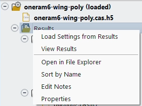
Loads the active settings of the Aero workflow steps from the Results folder Metadata (Settings → Results, Setup, Solution). These settings are generally those that are consistent with the most recent settings that were active when was last used.
Loads the sequence of all design point solutions in the Results directory for post processing using the Post-Analysis tool. A Post-Analysis node will appear in the Outline View and all out.*.dat[.h5] files will be loaded. The Dataset - Sequence slider in the Results ribbon can then be used to quickly navigate between each design point.
Deletes the selected case file.
Note: The command becomes active when using →
Caution: If you delete the case file that is used as the input case for the simulation, the simulation can no longer be loaded.
Opens the Results directory in the file explorer of the local operating system.
Sorts all files in the Results folder alphabetically by name. By default, the simulation files are sorted by time of creation.
Opens a Properties window showing the Notes panel, where you can add text notes to the selection. If a text note is added, the item inside the project view will be displayed with an * icon next to its name, signifying that a note has been added.
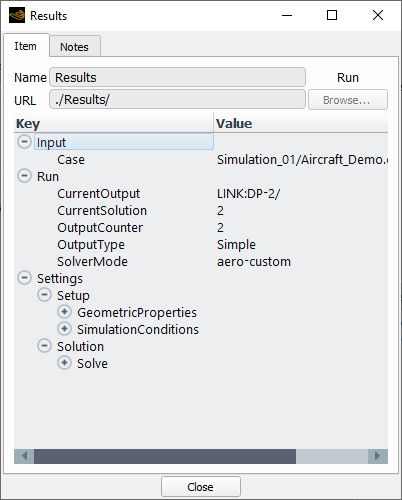
Opens a properties window showing the Metadata and properties of the Results. The figure below shows an example of the contents of a Results properties window.
Hidden contains flags used by the datamodel to know when to expose certain elements of the user interface. This information should not generally be required by you.
Input contains metadata that specifies the location of the input .cas[.h5] file used to generate the Results folder.
Run contains metadata that specifies the number of design points contained within the Results folder, and the CurrentOutput directory, related to the most recent design point that was calculated.
Settings → Setup → Geometric Properties contains metadata that stores the settings used in the Geometric Properties step when the Results were calculated. This metadata is used to restore the settings when loading a simulation.
Settings → Setup → Simulation Conditions contains metadata that stores the settings used in the Simulation Conditions step when the Results were calculated. This metadata is used to restore the settings when loading a simulation.
Settings → Solution → Solve contains metadata that stores the settings used in the Solve step when the Results were calculated. This metadata is used to restore the settings when loading a simulation.
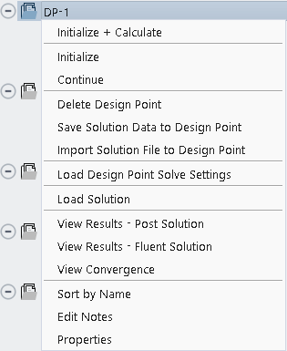
Initializes and then calculates the selected design point. This is equivalent to using the Solve → command from the Outline View with the respective design point Status in the Input:Design Points table set to . This option will execute a fresh start of your calculation. Any solution file that is already present will not be loaded – it will be deleted and will not be used as an initial solution. The calculation will take into account any changes in settings that were made to the Aero workflow steps in the Outline View.
Initializes the selected design point. This is equivalent to using the Solve → command from the Outline View with the respective design point Status in the Input:DesignPoints table set to . Any solution file that is already present will not be loaded – it will be deleted and will not be used as an initial solution. The initialization will take into account any changes in settings that were made to the Aero workflow steps in the Outline View.
Continues to calculate the selected design point. This is equivalent to using the Solve → command from the Outline View with the respective design point Status in the Input:Design Points table set to . This calculation will first load any previous solution file and continue the calculation from this previous solution. The calculation will take into account any changes in settings that were made to the Aero workflow steps in the Outline View.
Deletes the selected design point folder along with all the files contained within it. The remaining design point folder numbers and their files will be renamed to ensure that the project continues to have complete and sequential numbering. For example, if DP-2 is deleted, the previously named DP-3 folder and its content will be renamed to DP-2. This is equivalent to using the Simulation Conditions → command from the Outline View.
This command will save the current state of the solution in memory to the .dat file of the selected DP folder. This allows you to perform custom operations in the Solution workspace to prepare a data file, which can then subsequently save to a design point folder of choice. This may be helpful, for example, if you would like to prepare a solution with a custom initialization routine, before using to continue the design point calculation from that state. This option is only recommended for advanced users of Fluent Aero.
This can be used to select a solution file and load it into the design point folder, replacing the current solution (out.000X.dat.h5). The Status in the Input:Design Point table will be set to , as the contents of the tables will be out of date. To fill the tables with the values of coefficients and residuals associated with the new solution file, you must for 1 iteration.
Load all Properties - Solve panel settings from the design point Metadata (Settings → Solution → Solve) and populates the Solve step (including anything listed in ) with these settings. This is useful if you want to revert back to use Solve settings that were used for that particular design point.
Loads the design point solution file to memory and shows the solution file as bold in the Project View. This allows the selected solution to be post-processed from the Results node in the Outline View.
Opens the Post solution files (out.*.cas.post, out.*.dat.post) in a Post-Analysis post-processing session inside the Fluent Aero user interface. An object tree for Post-Analysis will be loaded in the Outline View and a Post-Analysis viewer will be loaded inside the Fluent Aero graphics window. The Post solution files are used only by post-processor tools and contain a sculpted subset of variables extracted from the standard Fluent solution files (out.*.cas[.h5] and out.*.dat[.h5]) allowing more lightweight post processing with surface variables appropriate for use with the Post-Analysis tool.
Opens the Fluent solution files (out.*.cas[.h5] and out.*.dat[.h5]) in a Post-Analysis post-processing session inside the Fluent Aero user interface. An object tree for Post-Analysis will be loaded in the Outline View and a Post-Analysis viewer will be loaded inside the Fluent Aero graphics window.
Note: In general, it is preferred to use the Post solution files with the Post-Analysis post-processing tool, if available. They are quicker to load by the post processor and contain a wider range of surface variables.
Load the convergence file of that design point in the convergence Plots window, using the Dataset: Custom. This allows you to conveniently investigate the convergence of a particular design point calculation directly from the Project View.
Sorts the design point folders alphabetically by name.
Opens a Properties window showing the Notes panel, where you can add text notes to the selection. If a text note is added, the item inside the project view will be displayed with an * icon next to its name, signifying that a note has been added.
Opens a properties window showing the Metadata and properties of the design point. The figure below shows an example of the contents of a Design Point properties window.
DP: Inputs contains the input parameters associated with the design point. These values are used to generate the Table:Summary accessible from the Tables → in the Outline View.
DP: Inputs: CustomInputs contains the custom input parameter names and values associated with the design point. This will only be shown if Simulation Conditions → Use Custom Input Parameters is , and a custom input parameter is defined.
DP: Inputs: CustomInputsBC contains the boundary specific custom input parameter names and values associated with the design point. This will only be shown if any boundary specific input parameters are set to in the Component Groups boundary list.
DP: Outputs contains the output parameters associated with the design point. These values are used to generate the Table:Coefficients, and Table:Forces accessible from the Tables → in the Outline View.
DP: Outputs: CustomOutputs contains the custom output parameter names and values associated with the design point. This will only be shown if Simulation Conditions → Use Custom Output Parameters is , and a custom output parameter is defined. These values are used to generate the Table:Custom Outputs accessible from the Tables → in the Outline View.
DP: Residuals contains the final residual values achieved at the final iteration calculated for the design point. These values are used to generate the Table:Residuals accessible from the Tables → in the Outline View.
All Settings: GeometricProperties, SimulationConditions, and Solve metadata will generally be the same as contained in it’s parent Results folder. However, if any of these settings were modified and a recalculate Selected Design Point was performed, these settings will be locally updated on the design point folder to correspond to these settings changes. If the metadata is the same as that of its parent Results folder, the text will be in italic font. If the metadata is different than that of its parent Results folder, the text will be in standard font.
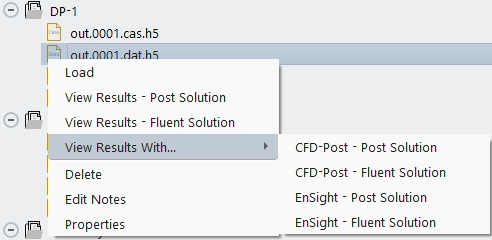
Loads the selected solution file to memory, and shows the solution file as bold in the Project View menu. This allows the selected solution to be post-processed from the Results menu in the Outline View.
Opens the Post solution files (out.*.cas.post, out.*.dat.post) in a Post-Analysis post-processing session inside the Fluent Aero user interface. An object tree for Post-Analysis will be loaded in the Outline View and a Post-Analysis viewer will be loaded inside the Fluent Aero graphics window. The Post solution files are used only by post-processor tools and contain a sculpted subset of variables extracted from the standard Fluent solution files (out.*.cas[.h5] and out.*.dat[.h5]) allowing more lightweight post processing with surface variables appropriate for use with the Post-Analysis tool.
Opens the Fluent solution files (out.*.cas[.h5] and out.*.dat[.h5]) in a Post-Analysis post-processing session inside the Fluent Aero user interface. An object tree for Post-Analysis will be loaded in the Outline View and a Post-Analysis viewer will be loaded inside the Fluent Aero graphics window.
Note: In general, it is preferred to use the Post solution files with the Post-Analysis post-processing tool, if available. They are quicker to load by the post processor and contain more surface variables.
Opens a CFD-Post post-processing session in a new window and loads the out.*.dat.post file associated with the selected file. This option is only available if the Post files have been written.
Opens a CFD-Post post-processing session in a new window and loads the selected file.
Opens an EnSight post-processing session in a new window and loads the out.*.dat.post file associated with the selected file. This option is only available if the Post files have been written.
Opens an EnSight post-processing session in a new window and loads the selected file.
Deletes the selected file.
Opens a Properties window showing the Notes panel, where you can add text notes to the selection. If a text note is added, the item inside the project view will be displayed with an * icon next to its name, signifying that a note has been added.
Opens a Properties window showing the Metadata and the properties of the case file.
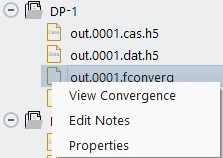
Load the convergence file in the convergence Plots window, using the Dataset: Custom. This allows you to conveniently investigate the convergence of a particular design point calculation directly from the Project View.
Opens a Properties window showing the Notes panel, where you can add text notes to the selection. If a text note is added, the item inside the project view will be displayed with an * icon next to its name, signifying that a note has been added.
Opens a Properties window showing the Metadata and properties of the convergence file.
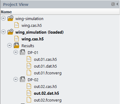
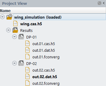
The Project View window will make use of bold text to provide additional information on Simulations, Case and Data file status.
A Simulation that is currently loaded and connected to a solver session will have its name be displayed in Bold with (loaded) listed next to the name.
The .cas[.h5] and .dat[.h5] files that are currently loaded will be displayed in bold. These files will also be specified as the Current files in the Simulation properties metadata window.
The image below shows an example of a Project View window that shows that the simulation wing_simulation is currently loaded, along with its case file wing.cas.h5, and its design point data file out.02.dat.h5.
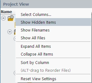
The Project View window can be sorted in various ways to help with file organization. By default, the Project View only displays the Name column in the Project View file organization panel. Right-clicking the Name column header will display additional file organization settings.
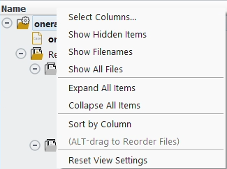
Opens a window that allows you to select the information to display in the Project View. Alternatively, this option can be selected by choosing Display → from the Project ribbon. See Using Columns in Project View for more info.
Shows additional folders and files that exist inside the Simulation and Results folders. See Hidden Items in Project View for more info.
Shows the exact file names used on disk for each item in the Project View.
Shows the full content of the Simulation and Results folders, including temporary files, log files, etc.
Expands all items in the Project View
Collapses all items in the Project View
Sorts all files by the selected Column. If the Name column is selected, the files will be sorted alphabetically. By default, the files in the Project View are sorted by order of creation.
Sorting by Alt-select-drag
In addition to the sorting options described above, all files can be moved up or down in the Project View by Alt -selecting the file and dragging it to a new position. This operation can only be performed on the default file organization view.
Resets the Project View to its initial settings. This will display only the Name column, and all files will be sorted by order of creation.
Sortable columns are available in the Project View window to show additional information and to help organize simulations, results and solution files.
By default, Project View only displays the Name column, which displays the Name of each item.
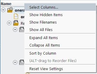
Right-click the Name column in the header and choose to open the column display menu. Alternatively, this window can be accessed by selecting Display → in the Project ribbon menu.
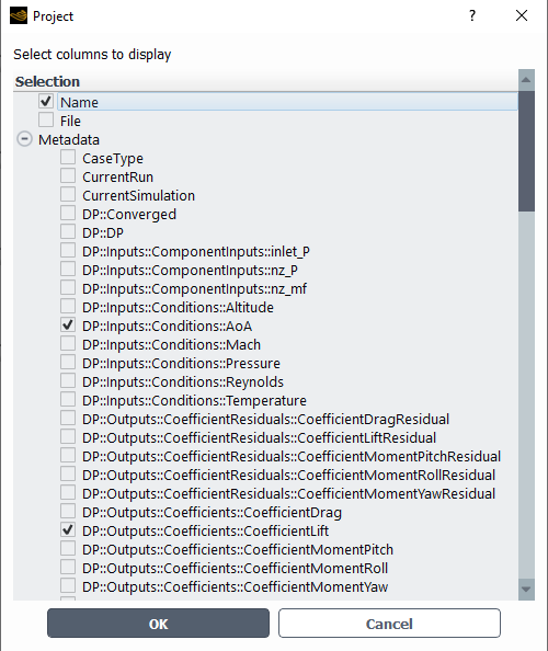
A window appears showing the list of metadata settings that can be selected to display as a column in the Project View. For example, DP::Inputs:Conditions::AOA and DP::Outputs:Conditions::CoefficientLift can be selected to display the Angle of Attack and Lift Coefficient associated with each design point.
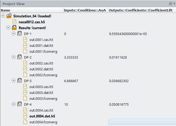
The selected information will then be displayed in a column to the right of the Name column. If the file contains a value associated with a display column, the value will be shown in the associated cell. If the file does not contain a property associated with a displayed column, the associated cell will be empty. In the image below, the columns show that 4 design points were calculated with different Angles of Attack (0, 3.33, 6.66 and 10 degrees) and resulted in a range of Lift Coefficients.
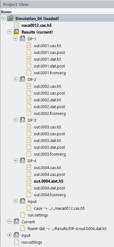
By default, the Project View only displays a selected list of case, result and convergence files as well as Simulation, Results and Design Point folders.
However, there are additional files associated with a project that you may want to interact with that are hidden by default. To display these files, right-click the Name column header and select .
Hidden folders and files will be shown.
Some of the hidden folders include the following:
run.settings file
This file contains all the Fluent Aero settings used to run the calculation and obtain the results for the simulation. This file is generated when you press . Whenever you reconnect to a simulation, this file is loaded and used to repopulate the Outline View settings and the Input: Design Points table settings.
Post Files
The Post solution files (out.*.cas.post and out.*.dat.post) are used only by post-processor tools and contain a sculpted subset of variables extracted from the standard Fluent solution files (out.*.cas[.h5] and out.*.dat[.h5]) allowing more lightweight post processing with surface variables appropriate for use with the Post-Analysis tool. These files will be present if Solution → Solve → Files → Write Post-processing Files is set to .
Current Folder
This folder contains links to all the current solutions, which typically will be the solution file that was most recently obtained from a calculation, or which was most recently loaded using a load command. When is used to open a simulation, the solutions listed in the current folder will be loaded and displayed in bold in the Project View menu.
Input Folder
This folder contains links to all case files or solution files that were used as an input to the simulation or results.