


The Aerodynamic Extraction Tool (AET) is an automated workflow intended to extract the performance characteristics of a rotor blade, and to produce airfoil performance definition files that can be used to define the rotor performance in Fluent’s Virtual Blade Model (VBM).
Fluent’s Virtual Blade Model (VBM) is a Blade Element Theory based approach to efficiently model rotating blades in a time-averaged manner in the context of a 3D simulation of an aircraft geometry. You can find out more detail about the Virtual Blade model in Fluent’s Virtual Blade Model in the Fluent User's Guide. To set up the model, VBM requires airfoil performance lookup tables to define the performance of each airfoil shape used in the rotor geometry, which include the lift and drag characteristics across a range of Angle of Attack, Mach and Reynolds numbers. These performance characteristics may be unavailable or difficult to obtain, they may not contain a sufficient set of conditions, or the airfoil shapes may be unknown. The AET workflow is designed specifically to alleviate these challenges, and to provide an automatic procedure to build these performance tables using CFD calculations.
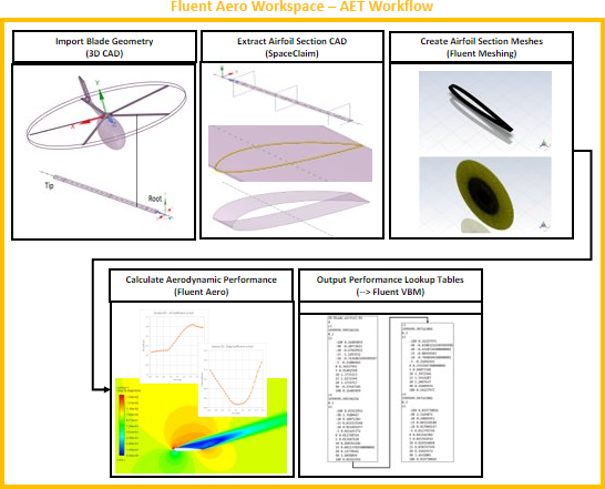
The AET workflow leverages the AnsysFluent Aero workspace project and simulation capabilities, along with the CAD capabilities of Ansys SpaceClaim, and the meshing capabilities of Ansys Fluent Meshing to automatically extract airfoil section CAD geometries, construct meshes, calculate and post-process solutions of spanwise airfoil sections of a 3D blade geometry using a wide range of conditions. The workflow guides you through the following steps:
Import Blade Geometry:
Select the 3D blade CAD geometry of the rotor blade that will be analyzed.
Alternatively, AET can select a 2D points definition file of a single airfoil section to extract the performance of this airfoil.
Extract airfoil section CADs (using SpaceClaim):
Perform multiple spanwise cuts of the 3D blade CAD to extract multiple airfoil sections using Ansys SpaceClaim as a background process.
Create Airfoil Section Meshes (using Fluent Meshing):
Generate 2.5D meshes of each airfoil section using Ansys Fluent Meshing as a background process.
Calculate Aerodynamic Performance of Airfoil Sections:
Calculate the aerodynamic performance of each airfoil using a range of conditions using Ansys Fluent Aero’s simulations and design points.
Output Performance Lookup Table Files:
Output and save performance lookup table files containing coefficients of lift and drag computed over a wide range of Mach, Reynolds and AoA. These files will be in a format that can be used to define a rotor directly in Ansys Fluent’s Virtual Blade Model.
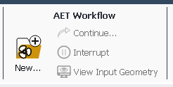
The primary AET workflow commands are available from either
![]() File or
File or ![]() Project.
Project.
The following set of commands are available in the menu:
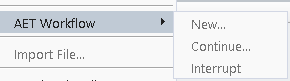
The following set of commands are available under ![]() AET
Workflow:
AET
Workflow:
![]() AET Workflow →
New...
AET Workflow →
New...
After creating a new project, the command will be made available. After selecting New..., a dialog will appear where you can select the mode ( or ) and the steps of the workflow you would like to complete.
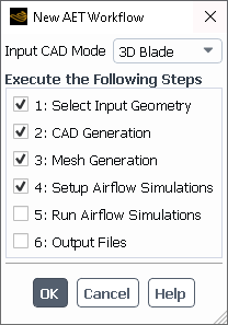
Input CAD Mode
If is selected:
A Select File dialog will appear where you can select an airfoil data points file (.txt).
When is enabled, a single 2.5D CAD will be generated from the input airfoil data points file.
When is enabled, a dialog panel will appear where you can specify the general settings to use for the Airflow Simulations.
If is selected:
A Select File dialog will appear where you can select a rotor CAD file (.scdoc).
When is enabled, a dialog will appear where the rotor section positions can be selected and the selected number of 2.5D section CADs will be generated from the blade geometry file.
When is enabled, a dialog panel will appear where you can specify the general settings to use for the Airflow Simulations.
Execute the Following Steps
Select the AET workflow steps to execute.
This step is used to define input geometry to the AET Workflow. This must always be selected. After clicking , a Select File dialog will appear where the input geometry can be selected. If Input CAD Mode is set to , a rotor CAD file (.scdoc/.iges/.pmdb/.part) can be selected. If Input CAD Mode is set to , an airfoil data points file (.txt/.dat) can be selected. Once the workflow starts, an Input file folder will appear in the Project View and the selected geometry file will be imported into that folder.
This step is used to construct the 2D CAD files of the airfoil sections that will be simulated in the AET workflow. Ansys SpaceClaim is used as a background scripted process to perform this step.
In mode:
A single CAD will be constructed from an airfoil data points file. The airfoil will be scaled to unit length.
In mode:
Multiple CADs will be constructed by extracting blade sections from a 3D blade geometry file. The airfoils will all be scaled to unit length. A Define Blade Sections dialog will appear where the blade section positions can be defined. If any of the selected blade sections share the same airfoil shape, only one CAD file will be generated to represent these sections.
In both modes, Ansys SpaceClaim is launched in batch mode to perform the step. Once the workflow starts, a CAD folder will be created in the Project View, and the input geometry file will be converted into 2D airfoil section CAD files (.pmbd) using a batch scripted Ansys SpaceClaim process.
Both the and CAD must meet certain conditions for use in the AET workflow. Refer to AET Workflow – Preparing the Input Geometry File for more information.
Note: Since this step uses Ansys SpaceClaim, which is only available on Windows, this step can only be performed on a Windows machine.
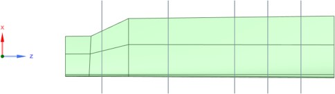
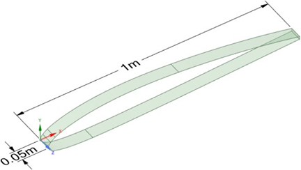
The two images below show selected blade sections extracted along a 3D blade geometry, and the resulting CAD that is produced for each section.
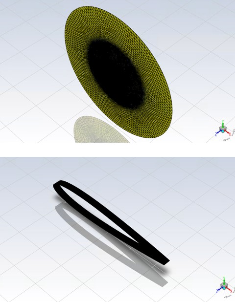
This step is used to construct the 2.5D Mesh files of the airfoil sections that will be simulated in the AET workflow. Ansys Fluent Meshing is launched in batch mode to perform the Mesh Generation step. The number of mesh files created will match the number of CAD files created in the step. Once the workflow starts, a Mesh folder will be created in the Project View, and the airfoil mesh files (.msh.h5) will be created.
Each mesh will consist of about 135k prism and hexahedral cells. A 2.5D mesh refers to a 2D mesh that is extruded to be 1 layer thick in the spanwise direction. The limits of the computational domain are defined by a cylindrical boundary that acts as a pressure farfield and a flat circular boundary defined as a symmetry plane in the Z direction. Mesh refinement is made in all directions away from the airfoil to capture wakes produced by all possible AoAs from 0 to 360 degrees.
This step is used to create the Airflow Simulations associated with each airfoil. The number of airflow simulation folders will match the number of airfoil mesh files created in the Mesh Generation step. A Setup Airflow Simulations dialog will appear where you can specify various general airflow simulation settings, such as the range of input Mach, Reynolds and AoA to simulate as design points, and the umber of iterations to solve for each design point. Once the workflow starts, an Airflow simulation folder will be created for each airfoil mesh file.
This step is used to calculate all design points of all airflow simulations on each airfoil. Once the workflow starts, Fluent Aero will sequentially connect to each airflow simulation in the Project, and calculate every design point that requires update.
This step is used to post process the airflow simulations for all airfoils, and to export a txt file (.dat) for each airfoil that contains the airfoil performance data in a friendly format for Fluent’s VBM.
![]() AET Workflow →
Continue...
AET Workflow →
Continue...
The Continue... command can be used to restart or continue an already created AET workflow. This command will become available as long as a new AET workflow project was created and at least the Input CAD was imported.
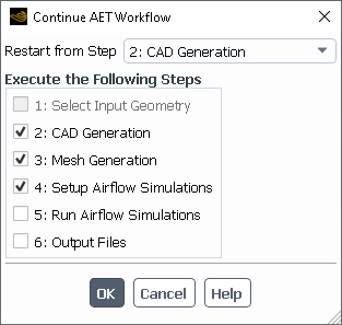
Restart from Step
Select the step from which the AET workflow will be restarted. All later steps that have already been calculated will be cleaned up and deleted. Any step that is enabled with a check box using the Execute the Following Steps will also be executed.
Execute the Following Steps
Select the AET workflow steps to execute after pressing .
![]() AET Workflow →
Interrupt...
AET Workflow →
Interrupt...
This will immediately interrupt the current AET workflow step that is being executed. After interrupting, you may continue the AET workflow step again starting from the step that was interrupted.
![]() AET Workflow → View Input
Geometry
AET Workflow → View Input
Geometry
This command can be used to view the input 3D CAD geometry in a separate SpaceClaim window. After clicking this command, a separate SpaceClaim window will open and the 3D blade geometry will be loaded in that window. This new window can be used to view the geometry, make measurements (to determine where to place the section cuts, for example), or to cleanup, repair and save updates to the input geometry. This command is only available in mode and if the input geometry has already been imported.
For each AET workflow step that is executed, an associated popup dialog menu may appear to allow you to specify relevant settings to that step. The dialogs are described below.
Define Blade Sections
This dialog box will appear if a 3D blade geometry is used, and if step is selected. It is used to select the airfoil sections to be extracted from a 3D blade geometry.
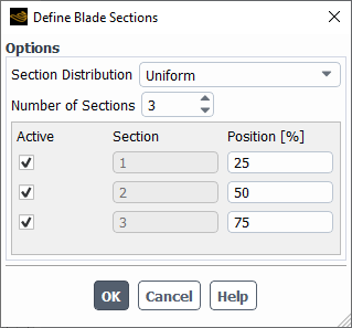
Section Distribution
If is selected, the section positions will be automatically computed. If is selected, the positions can be entered manually.
Number of Sections
Choose the number of sections to use to represent the blade.
Active
Enables or disables the specific section position to be considered by the AET workflow.
Section
The relevant section number associated with the position. This entry is not editable.
Position [%]
The radial position of the section in %. A 100% value refers to the position of the tip of the blade. A 0% value refers to the position of the point of rotation (this is likely not aligned with any airfoil section of the blade geometry).
Note: When selecting the radial positions to extract the airfoils of the 3D blade, it is important to ensure that the minimum radial position is located at a point where the blade geometry exists. If the radial position on the 3D blade geometry does not contain an airfoil section, there will not be any section extracted from the CAD and the workflow will stop and output a warning identifying the issue. In this case, you should restart the AET workflow from the CAD Generation step and must select a section within the blade.
Mesh Generation
This dialog box will appear if has
already been attempted in the project, ![]() AET Workflow
→ Continue... is used and only is selected. This dialog is used to remesh a selected number
of airfoil sections.
AET Workflow
→ Continue... is used and only is selected. This dialog is used to remesh a selected number
of airfoil sections.
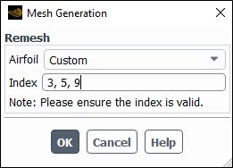
The following options are available:
Remesh
Airfoil
Select the airfoil sections that you would like to remesh. Select to remesh all the airfoil sections. Select to remesh any airfoil sections that are greater or equal to the number entry in the Index box. Select to set a custom list of airfoil sections to remesh in the Index box.
Index
This option is revealed if Remesh → Airfoil is set to or . Enter either the starting section to remesh or a list of comma separated remesh sections.
This panel is useful if you would like to restart a previously failed mesh generation step (for example, if the tool crashed or if the mesh generation of a certain section was unsuccessful).
Furthermore, if you would like to change the mesh settings used to remesh an airfoil section, advanced users could edit the mesh control files before performing the remesh operation. The following files could be edited:
airfoil*-2D-remeshing.jou: The journal file that controls the airfoil section mesh creation process.
airfoil*-2D-meshingSizes.scm: A definition file that defines various mesh sizes used to create the airfoil section mesh.
Note: Fluent Meshing will use the parameters inside the mesh settings file to compute a virtual Size Field throughout the domain and generate the 2.5D mesh. The file contains two parts, the header and mesh settings. The header indicates the section information on which Fluent Meshing will generate the 2.5D mesh. It then refers to a list of parameters located within the file which are used as inputs. The mesh settings are parameters used by Fluent Meshing to compute a virtual Size Field throughout the domain and generate the 2.5D mesh. Below is a brief description of this list of parameters:
Header
currentSection– Section name.currentSectionFile– Input section's 2.5D CAD.chord– Chord length of the input section’s 2.5D CAD. Keep the recommended default of 1 m.scaleFactorCAD– Scale factor of the output 2.5D mesh. Keep the recommended default value of 1.currentOutput– Output mesh file’s name.
Mesh Settings
z-span– Spanwise length of the input 2.5D CAD. Keep the recommended default of 0.05 m.mpx/y/z– Coordinates of the material point defined within the 2.5D domain.globmin/max– Minimum and maximum global cell size of triangles or tetrahedra used during the wrapping and mesh creation.Important: Any other surface mesh sizes defined within this file must be within this range or else the mesh operation will fail.
curvmin/max– Minimum and maximum cell size used to capture the curvature of wall surfaces. This is used for surface mesh creation.curvgrowth– Growth rate of the cell size used to capture the curvature of wall surfaces. This is used for surface mesh creation.curvangle– Difference between the normal angle of two neighboring wall cells. This value is used to identify curved locations where the minimum cell size should be applied. The default value of 1 is suitable for most airfoil geometries.db01– Cell size applied to the outmost body of influence (BOI), which is a geometry surrounding the 2.5D airfoil and is provided as a template.db02– Cell size applied to the inner body of influence (BOI), which is a geometry surrounding the 2.5D airfoil and is provided as a template.dbte– Cell size applied to the body of influence (BOI), which is a geometry surrounding the 2.5D airfoil’s trailing edge (TE) and is provided as a template.prismFirstHeight– First layer height of the prisms which will be generated and attached to the 2.5D airfoil’s wall.prismGrowthRate– Prism’s growth ratio from the wall surface, starting from the first layer.prismNum– Total number of prism layers to be generated.proxmin– Minimum cell size used in proximity of the surface. This is used for the surface mesh creation when a blunt trailing edge is present in your 2.5D airfoil geometry.proxNum– Number of cells filled between two proximal surfaces. This parameter is useful when you have a blunt trailing edge in your geometry. It will assign a given number of mesh cells over the blunt surface of the trailing edge.
After remeshing a particular airfoil section, the AET workflow will identify if
the old mesh associated with that airfoil section was previously used to create an
Airflow simulation folder using that old mesh. If an
Airflow simulation folder was identified using that old mesh,
the simulation will be deleted and a new simulation folder will be created with the
new mesh of that airfoil section. To recompute the airflow simulation using this new
mesh, you can use ![]() AET Workflow →
Continue... and select .
AET Workflow →
Continue... and select .
Setup Airflow Simulations Dialog
This dialog box is used to define some common initial settings to be used in all Airflow simulations.
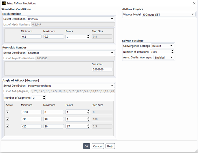
Simulation Conditions
The settings in this section are used to define the matrix of freestream conditions to use as design points. Mach Number, Reynolds Number and Angle of Attack [degrees] conditions can be provided. For each input parameter, Select Distribution can be used to set the distribution to a value or distribution. Specifically for the Angle of Attack [degrees], a distribution can be selected. Depending on the distribution type selected, the content of the associated gray box below will be adjusted. Once the entries are specified into the gray box, the final list of input values is displayed next to List of Mach Numbers, List of Reynolds Numbers and List of AoA [degrees]. The final design point list used for each airflow simulation will contain every combination of the values of these three input variables.
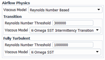
Airflow Physics
In this section, set ViscousModel and Corner Flow Correction when the AdvancedSettings flag is enabled. If Reynolds Number Based is set as the Viscous Model, you can specify the ReynoldsNumberThreshold and Viscous Model for Transition and Fully Turbulent flows. For design points with a Reynolds number below the transition threshold, the laminar viscous model is applied.
Solver Settings
Select some common solver settings to use for all airflow simulations, such as Convergence Settings, Number of Iterations and Aero. Coeffs. Averaging.
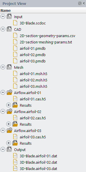
The Project View directory structure can be used to keep track of the progress of the AET workflow. Each folder created in the Project View is associated with a particular step in the workflow.
Input
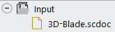
This folder is associated with which is used to import the input geometry for the AET Workflow. After completion of this step, this folder will contain an imported geometry file, the type of which depends on the selected Input CAD Mode.
In mode, this will be a .scdm/.pmdb/.part CAD file of a single rotor blade, oriented along the z axis.
In mode, this will be a .txt/.dat points file to describe an airfoil section.
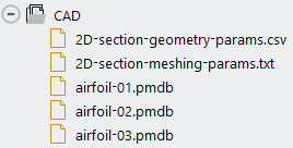
CAD
This folder is associated with , which uses Ansys SpaceClaim in batch mode to generate 2D CAD files of the selected airfoil sections.
In mode, the 3D rotor geometry will be imported into Ansys SpaceClaim, and multiple 2D airfoil sections will be extracted. The inputs to define the airfoil sections are set in the Define Blade Sections dialog. If any of the selected blade sections share the same airfoil shape, only one CAD file will be generated to represent these sections.
In mode, the file will be imported into Ansys , and a 2D geometry will be created.
Important: This step can only be executed on a Windows machine.
Once this step is complete, a CAD folder will appear in the Project View containing the individual airfoil section CAD files and other .txt files to describe these sections.
2D-section-meshing-params.txt
Specifies the mode, number of sections, section names, and section chord lengths of the 2D section CADs produced.
2D-section-geometry-params.csv
Descriptive geometry information about the blade and defined sections. This can be used as a reference for later steps.
OUT-TMP-WORK.scdoc
Temporary SpaceClaim CAD file used to store intermediate steps of the CAD generation process. This file is not used in later steps.
airfoil-0#.pmdb
2.5D section CAD file produced by the step in .pmdb format. This is used in the subsequent meshing step.
airfoil-0#.scdoc
2.5D section CAD file produced by the step in .scdoc format. This is not used in the subsequent meshing step.
Additional files may appear in the disk location of this folder but are not shown in the Project View. These include:
sc-script.scdoc
Temporary Ansys SpaceClaim CAD file used to store intermediate steps of the CAD generation process. It contains all geometries throughout the SpaceClaim process. This file is not used in later steps.
sc-script.log
Log output of all Ansys SpaceClaim operations performed during this step.
sc-script.png
In mode, this file will contain a picture showing the position of each extracted airfoil section overlaid on top of the input 3D blade geometry. In mode, this file will contain a picture showing the 2D airfoil constructed from your input file.
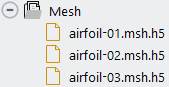
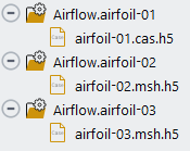
Mesh
This folder is associated with , which uses a separate Ansys Fluent Meshing process in batch mode to generate 2.5D Mesh files of the selected airfoil sections. Each section CAD that was constructed in the previous step will be meshed, resulting in the same number of airfoil-0#.msh.h5 files as there were airfoil-0#.pmdb files produced in the prior step.
Once this step is complete, a virtual Mesh folder will appear in the Project View with the individual section Mesh files, as shown below.
The files produced are briefly described below:
airfoil-0#.msh.h5
2.5D section mesh file produced by the step. This is used in the subsequent step.
Additional files may appear in the disk location of this folder but are not shown in the Project View. These include:
airfoil-0#-fluentMeshing.log
Transcript output file of all Ansys Fluent Meshing operations performed while constructing this airfoil mesh.
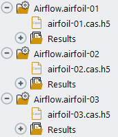
Airflow
These folders are created when is performed. An Airflow.airfoil-0# simulation folder will be created for each airfoils-0#.msh.h5 that was created in the previous step.
These Airflow simulation folders are the same as typical airflow simulations that one would create when using Fluent Aero’s command. However, the default settings used in these airflow simulations are partially defined by the Setup Airflow Simulations dialog that appears when is selected.
If the default settings are used, each simulation will contain a large number of design points. After these airflow simulations are created using , you can decide to connect to these simulations manually and adjust their settings as needed.
The results for these simulations are calculated when is executed. When executing this step, Fluent Aero will sequentially connect to each Airflow simulation and calculate all design points. Since it is possible to use a large number of airfoil sections and a large number of design points for each airfoil, you may decide to use a compute cluster to perform these calculations. When performing the step, only the design points that have not already been updated (for example, their Status is not ) will be calculated.
Output
This folder is associated with . In this folder, you will find a summary of the convergence of the simulation design points of all airfoil simulations and data files summarizing each airfoils performance which can be used to define a rotor in Fluent’s Virtual Blade Model (VBM).
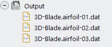
The files produced are briefly described below:
Geometry.airfoil-0#.dat
Airfoil performance data files, containing the lift and drag lookup tables associated with design point calculations of each Airflow simulation. These files are in a format such that they can be used to define airfoil section performance in Fluent’s Virtual Blade Model (VBM) when defining a VBM rotor.
Table-All-DPs-Summary.csv
This file summarizes the input flight conditions, calculation residuals and convergence of all design points in each Airflow simulation. The content of this file is similar to the Table-Summary.csv file that is produced by each individual simulation. However, since it combines the results of all simulations, it contains an additional column specifying the Airflow simulation name.
Furthermore, after the step is performed, three new panels will appear above the Graphics panel that summarize the convergence of all simulations and design points.
Convergence
Table: All DPs Summary
Table: Simulations Summary
Convergence
Once has been executed, a Convergence panel will appear above the Graphics panel which provides access to view the convergence history of any design point in any simulation. The Dataset drop-down selection can be used to select the simulation name and design point number.
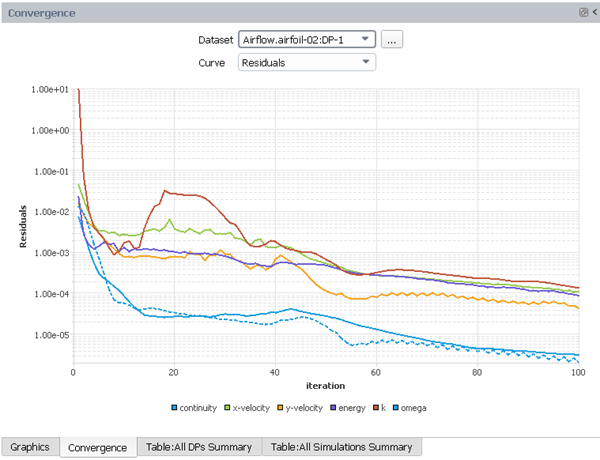
Table: All DPs Summary
Once has been executed, a Table: All DPs Summary panel will appear above the Graphics panel. For every design point, a summary of input parameters, residual averages and convergence criteria will be displayed. This information is also outputted to the Table-All-DPs-Summary.csv file shown in the Output folder of the Project View.
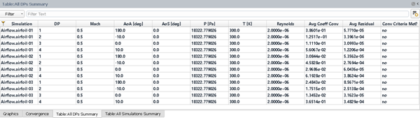
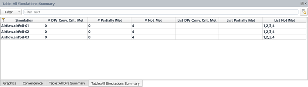
Table: All Simulations Summary
Once has been executed, a Table: All Simulations Summary panel will appear above the Graphics panel. A summary of how many DPs have met, partially met, or not met the default convergence criteria will be shown. This information can be helpful in identifying the design points that should be recalculated to obtain more reliable results.
The goal for the AET workflow is to allow you to work through the steps in a sequential fashion automatically without the need to go back and perform previous steps. However, one step in particular that might require more attention is 5: Run Airflow Simulations. If there are design points that have not converged sufficiently to provide an accurate/precise solution, you may need to go back and simulate that design point again with more robust solver settings before re-creating the Output files. The steps below provide a typical example of this workflow.
Note: There are many ways one could manually interact with the airflow simulations to improve the convergence of design points. The steps shown below are simply a useful example of a possible way to do this. However, whenever a design point calculation is updated, you must afterwards ensure to also update the Output folder so that the new results are used and properly saved for its correct usage by Fluent’s VBM.
Example 3.1: Example Steps to Improve the Convergence of a Specific Design Point
You have completed a full run of the AET workflow.
After has been run.
Go to Table: All Simulations Summary. The summary shows that most design points have either met or partially met the convergence criteria. However, DP-5 from has not met the convergence criteria.
Go to Table: All DPs Summary. Notice that AoA [deg] associated with this design point is 20 degrees. This is a high angle of attack and the solution might yield to a transient solution or to near stall condition.
Go to the Convergence panel and set the Dataset to . Select . Notice that the value of is oscillating with a substantial amplitude, suggesting that the solution is unstable. This is preventing the convergence criteria from being met.
You could either improve the convergence of this design point or delete the design point from the dataset before recreating the output files. The following steps will show an example of how to potentially improve the convergence.
In the Project View, right-click the Airflow.airfoil-01 simulation folder and select .
Once the simulation is loaded, set the Status of to in the Input:Design Points table.
Go to
 Solution → Solve.
Change the Convergence Settings to different
settings that you believe will improve the convergence of this design
point. For example, change Convergence Settings
from to or to
and edit the advanced parameters that are
displayed. You can also increase the Iterations from
Solution → Solve.
Change the Convergence Settings to different
settings that you believe will improve the convergence of this design
point. For example, change Convergence Settings
from to or to
and edit the advanced parameters that are
displayed. You can also increase the Iterations from
1000to2000.Next, select
Simulation
Conditions . This will cause the status of
DP-5 to be saved to the project as .
. This will cause the status of
DP-5 to be saved to the project as .Close the simulation and click to save the case and settings.
Select
 File → AET
Workflow → Continue.... In the
panel that appears, set the to
and ensure both
and are selected. Click
.
File → AET
Workflow → Continue.... In the
panel that appears, set the to
and ensure both
and are selected. Click
.When is executed, Fluent Aero will identify that the Airflow.airfoil-01 simulation has a single design point that requires update and it will connect to that simulation and recalculate that particular design point. Since no other design points require update, no other design points will be recalculated.
When is executed, the Output files will be recreated and the Summary and Convergence tables will appear. Investigate these tables to ensure Airlfow.airfoil-01:DP-5 has now converged.
Note: Alternatively, instead of using to recalculate the design point, you could
recalculate it manually while connected to the simulation right after
you edit the Solve settings. If you take this
approach, you should ensure to recreate the output files manually using
![]() File → AET
Workflow → Continue... and
setting Restart from Step to .
File → AET
Workflow → Continue... and
setting Restart from Step to .
Right-click an Airflow simulation folder to use this command. When selected, the settings of the simulation (as contained in the run.settings file) will be copied to all other simulations in the project that do not yet have any results calculated. After the airflow simulations have been created using , this command can apply custom settings to all airflow simulations by performing:
Load one of the airflow simulations.
Use the Outline View to modify any settings under Setup or Solve.
Close the simulation and selecting to save the settings.
Right-click the simulation and select . The settings of the selected airflow simulation will be copied to all others in the project that do not contain results.
Right-click an Airflow simulation folder to use this command. When selected, a Convergence window will appear where the convergence histories of all the design points of all simulations in the project will be displayed. This command is available even if a user does not have a simulation loaded.
Right-click in the Outline View to use this command. When selected, the currently selected Status of each Design Point in the Input:Design Points table will be saved. Use this command to force certain design points to be set to such that they will be calculated when is used.
aetSetLogLevel(level)Type
aetSetLogLevel(level)into the python console to use this command. Use this to set the amount of log information you want displayed in the Fluent Aero Console from the SpaceClaim and Fluent Meshing steps. Regardless of the selection, the full log for each step can still be found under Mesh/fluentMeshing.log and CAD/sc-script.log files.evel = 1 (default)- Show a reduced log output, to show all log lines containingInfo:andError –typically resulting in about 10-20 lines of log information shown.level = 2– Show the full log output, typically resulting in hundreds of lines of log information shown.level = 1– Show no log output of the Fluent Meshing and SpaceClaim subprocesses. Setting this will also skip the error checking/management, which will allow each subprocess to continue, even if an error message appears in the process.
The input geometry file, whether it is a file or a file, must be prepared to meet certain conditions to be supported by the AET workflow.
2D Points File Requirements
The file must be a text file with two columns, one for the X position and one for the Y position, with a space in between the columns.
The file should be plain text format and should use the .txt or .dat suffix.
The coordinates must be in unit length.
The file must contain the coordinates of the airfoil only.
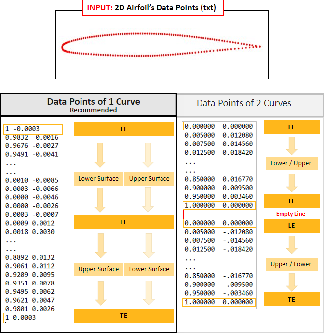
The file must consist of either one or two curves of data points. One curve is recommended.
If one curve is used, the data points should start from the trailing edge, then wrap around the airfoil up to the leading edge and finally back to the trailing edge at the end.
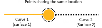
If two curves are used, each curve should start at the leading edge and end at the trailing edge. An empty line should be placed between the two curves. The script used in will combine these two curves into a single curve before proceeding with the next step.
3D Blade File Requirements
The file should be in .scdoc, .pmdb, .iges or .part format. The Ansys SpaceClaim .scdoc format is recommended.
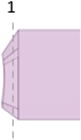
Only one rotor blade should be included in the file. The blade geometry can be either in one body object or several separated surface objects as shown below:
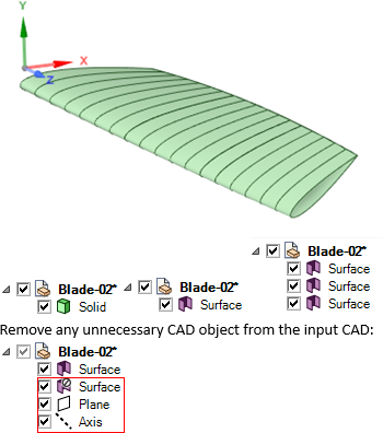
The SpaceClaim script will automatically select all objects inside the input CAD file to merge into the final blade geometry.
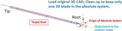
The blade should be positioned such that the center of rotation of the rotor is at the global origin.
The blade span, or rotation radius line (R) of the blade, should be aligned with the +Z axis.
The rotation axes of the blade should be aligned with the +Y axis.
3D Blade Geometry Limitations
The AET workflow supports 3D blade geometries with large twist angles (-90 and +90 degrees).
Best Practices for Preparing the 3D Blade
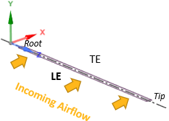
The 3D blade geometry is required to be orientated such that the span is positioned along the +Z axis, the chord is positioned along the +X axis, and the blade is rotating around the +Y axis, with the center of rotation located at the point of origin, as shown below:
In addition to orienting the blade to the required position, your blade CAD should be cleaned up to ensure a water-tight geometry. Some guidelines are described below:
In the most ideal case, all blade surfaces should align at common edges, without overlapping and without gaps, as shown in the image below.
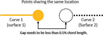
It’s sometimes not possible to ensure a perfect CAD, so the AET workflow is able to automatically repair small gaps between two connecting surfaces. Any gaps with a local tolerance of 0.5% chord length will be automatically closed. However, if there is any gap larger than 0.5% of the local chord length existing in your geometry, the blade CAD should be cleaned up manually to ensure your geometries’ surfaces are watertight.
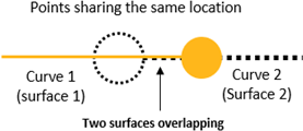
The AET workflow is also able to automatically repair slight overlapping surfaces. However, if two surfaces are overlapping in a particularly complex manner, it is recommended to clean the blade geometry to remove these overlapping surfaces.
Complex shapes used to describe the trailing edge (TE) may cause difficulty for the AET workflow. Therefore, the input blade should not capture too much detail or contain messy CAD definition of its TE geometry. Try to clean up the blade’s TE so that the TE has a simple shape, such as simple sharp, blunt, or rounded shape.
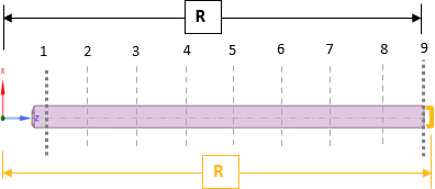
Finally, after you have prepared the 3D blade CAD, you should consider defining the airfoil section cuts you will use in the AET workflow. An overall view of 9 section cuts is shown below:
Avoid defining a section at exactly the maximum R value, which represents the blade tip. The highest section cut should be defined far enough away from the blade tip such that a complete airfoil section is obtained.
Avoid defining a section at the blade root, where a geometry may exist for mechanical purposes but does not represent an airfoil shape. Typically, such section should not contribute substantially to the rotor disk load.
Python commands are available by either:
Launching each individual step of the AET workflow (one command line for each step).
Launching the entire AET workflow (one command line for all steps).
Both of these commands can be easily launched using journal files to record your actions from the AET workflow to a python script file.
![]() File → Start Journal...
File → Start Journal...
See below for example python commands used to launch the AET workflow using one command line per step (with some additional lines to control sequencing if launched simultaneously):
Project.aetCleanup('step1Input') • Project.aetInputFiles('3D
                        Blade', 'T2-Blade.scdoc')
Project.aetBladeToCAD_SC('True', 'Custom', '3', '0.3,0.8,0.8001')Project.aetCADToMesh_FM('True', ‘True’, ‘False’, ‘False’)import os, timeprjFolderPath = "/path/to/aetproject.cffdb/"while not os.path.exists(os.path.join(prjFolderPath, 'Mesh', 'proc.e')): time.sleep(2)Project.aetSetupSims(['Constant,0.7,False,False'], ['Constant,2000000,False,False'], ['Piecewise-Uniform,"-20,-90,180","20,90,0","3,2,1"'], ['10,Default,K-Omega SST,Enabled'])Project.aetRunSim('Airflow.airfoil-01')Project.saveCase()waitFalse(csim().Solution.RunState.ClientProcessRunning)Project.aetCloseSim('Airflow.airfoil-01')Project.aetRunSim('Airflow.airfoil-02')Project.saveCase()waitFalse(csim().Solution.RunState.ClientProcessRunning)Project.aetCloseSim('Airflow.airfoil-02')Project.aetOutputFiles(True)
See below for example of a python command used to launch the entire AET workflow using a single command:
Project.runAETWorkflow('T2-Blade.scdoc', '3D Blade',
                        '[True,True,True,True,True,True]', '[True,\"Custom\",3,[0.3,0.8,0.8001]]', ,
                        ‘()‘,
                        '[[\"Airflow\",[[\"Mach\",[\"Constant\",[0.7]]],[\"Reynolds\",[\"Constant\",[2000000]]],[\"AoA\",[\"Piecewise-Uniform\",
                        [[-20,90,-180],[20,90,0],[3,2,1]]]]]],[\"Solve\",[[\"Turbulence
                        Model\",\"K-Omega SST\"],[\"Convergence
                        Settings\",\"Default\"],[\"Iterations\",1000],[\"Aero. Coeffs.
                        Averaging\",\"Enabled\"]]]]')
Limitation
Ensure to use only one escape character (\) per instance of
a quotation mark (“) in this single line
implementation.