


Use the Import CAD and Part Management task to import one or more CAD files into your simulation and to perform selective management of which parts you may want to include in your simulation, if needed. Selected parts are then designated as potential meshing objects, where selective settings can be adjusted as desired. Upon completing the task, meshing objects are created for later use in your Fluent simulation.
You can import one or more CAD geometry files into your workflow, as well as append additional files as needed. Once specified, you can determine how the portions of your CAD geometry will be converted into meshing objects for your simulation: automatically by part, or by manually choosing your custom parts or assemblies.
Upon loading the CAD geometry, you can view the components of the CAD geometry in the CAD Model tree. You can also view potential meshing objects in the Meshing Model tree. Various properties for your meshing objects (such as feature extraction angle, or custom refaceting settings) can be viewed and adjusted accordingly. When you are satisfied with your meshing model objects and their properties, you can complete the task, thereby creating meshing objects for later use in your Fluent simulation.
Note: You can work more easily in this especially complicated task by detaching, relocating, and resizing the editor portion of this workflow task. See Editing Tasks for more information.
Note: A modified version of this task (designed only for appending CAD files) is also used when replacing CAD parts (see Choosing Part Replacement Options for more information).
For the CAD File field, provide a path and a name for the CAD file that you want to load into the task, or use the (…) button to browse for a specific file.
Standard ANSYS file types are supported, including
.scdoc,.scdocx,.dsco,.agdb,.fmd,.fmdb,.pmdb,.tgf, and.msh*.Other CAD formats are also supported, including
.jt,.plmxml,.stl,.CATPart,.CATProduct,.prt,.x_t,.sat,.step,.iges, and.igs. See, for example, File Format Support for additional formats.To quickly import multiple CAD files, you can use basic wildcard expression patterns such as the * or ? wildcards. For instance, to import multiple STL files, you can use
*.stlin the CAD File field.Select an appropriate Import Route option, or keep the default value, depending on your requirements and platform. In most cases, the default value is recommended and should lead to the desired data being imported, however, you should be aware of and verify the CAD configurations being made because they may be considered during import. See CAD Integration for details.
The workflow uses an
.fmdfile to extract and persist CAD information for this task. To generate an appropriate.fmdfile, the available options for the Import Route depend on the selected CAD File, and your particular platform (Windows or Linux). The various Import Route options include:The Native option loads the CAD file natively into FM, and internally generates an FMD file that is then loaded into the workflow. This option is available for
.fmd,.fmdb, and.stlfile formats.Note: Using this import route, the CAD data should not differ across Windows and Linux for default settings.
The SCDM option uses ANSYS SpaceClaim Direct Modeler to read the CAD file and internally generates an
.fmdfile that is then loaded into the workflow. You may also want to note any SpaceClaim file options that you may have configured.Note: This route is only available on Windows, and is not available on Linux.
The DSCO option, available only when Discovery is installed, allows you to import Discovery (
.dsco) files.The Workbench option uses Ansys Workbench CAD readers or plug-ins to attach or load the given CAD file and generates an
.fmdfile that is then loaded into the workflow.Note: This route is available on Windows and Linux., though not all formats are supported on Linux when compared to Windows. Also, third-party add-on modules can lead to slightly different CAD data upon import (for example, names, assembly hierarchy, etc.).
The ACIS option is the default import route for
.saband.satfile types.The MSH option is the default import route for
.tgf,.msh.h5, and.mshfile types.Note: While importing
.msh*files as faceted CAD geometries, zone naming will be influenced by pre-existing labels in the.msh*files. If this is not desired, then, before importing the files, remove the labels from the.msh*files. Otherwise, if certain zone names are desired, then labels can be used to control the naming.The JTOpen option is the default import route for
.jtand.plmxmlfile types, and only faceted data is imported.Note: The JTOpen option is available on more recent Linux OS variants (requiring a
glibcsupplying'memcpy@GLIBC_2.14'), that is, it is not supported on Red Hat / CentOS 6 series.
For selected
.stlfiles, use the File Unit field to indicate the units in which the file was created.Note: Imported
.stlfiles can have different sets of units.For selected
.jtfiles using the JTOPEN import route, you can use the Jt LOD field to choose the level of CAD tessellation accuracy (level of detail) exposed after import. For example, typically, you might have three levels of detail (such as, 1 for 'fine', 2 for 'medium', and 3 for 'coarse') but up to ten might be contained in the.jtfile. If a certain level of detail does not exist in the file, the next finer level of detail is taken automatically.Enable the Part per body option to import the CAD geometry such that all bodies are available as individual parts when the geometry is loaded into the CAD Model tree.
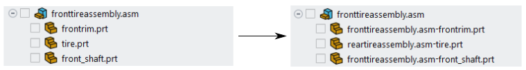
(optional) You can choose to apply a special part naming convention through the Settings drop-down button by selecting the Prefix component name option. Once selected, and when the file is loaded into the CAD Model tree, the names of the geometry's individual parts are prefixed with the names of their corresponding components.
The naming convention is applied to the names of the objects in the Meshing Model tree as well, whether they are created on a per-part basis or using a custom approach.
In addition, the Remove empty components option, enabled by default, removes any empty CAD components while loading the CAD file.
Select an option from the Create Meshing Object Per field.
Choose One per part so that Fluent automatically creates meshing objects for all the parts within the CAD model.
Choose Custom to be able to manually assign which parts of your CAD model are to be included as meshing objects in your simulation.
Use the Display Unit field to specify the units that you want to work with when the geometry and mesh is displayed in the graphics window. This field also specifies the dimensions of the generated mesh.
The workflow will display the units in the graphics window next to the ruler and while calculating distances (for example, when using the Distance tool in the Ribbon).
When the Import Route is set to Workbench, you can use the Settings drop-down button to select additional CAD import settings, such as:
Ignore Solid Names: (for
.stlfiles) allows you to import your CAD geometry while ignoring the names assigned to solids.Note that binary STL files contain a single solid and may have an associated solid name, whereas ASCII STL files contain one or more solids and each can have a solid name. The Ignore Solid Names option allows to control whether or not to use the name contained in the STL file for naming mesh objects and components.
Import Solid Bodies: allows you to import solid bodies along with your CAD geometry.
Import Surface Bodies: allows you to import surface bodies along with your CAD geometry.
Import Line Bodies: allows you to import line bodies along with your CAD geometry.
Use the Load button to load the CAD file into the task.
Note: You can append additional CAD file(s) to your currently loaded CAD file. See Appending CAD Files for details.
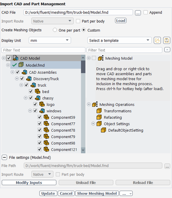
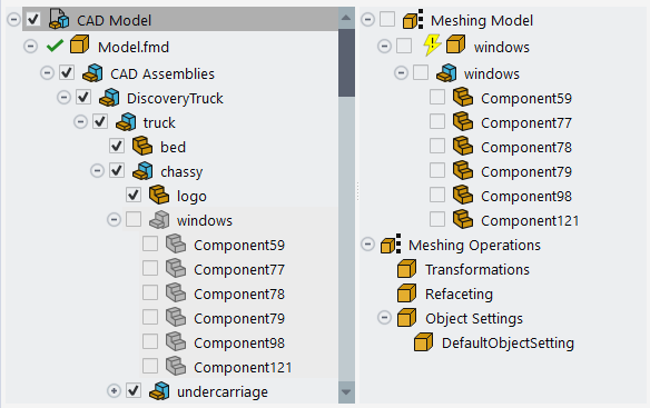
Use the CAD Model tree to visualize the hierarchy of your CAD model. By default, the CAD Model tree is automatically populated with the components of the imported and/or appended CAD file(s). For more information, see Working with the CAD Model Tree
Note: If you have read in a previously generated mesh created from another fault-tolerant workflow session, you need to click the Load button to reload the CAD file into the task and to see its components in the CAD Model tree.
Use the Meshing Model tree to visualize the hierarchy of your meshing objects.
If Create Meshing Objects Per is set to One per part, the Meshing Model tree is automatically populated with all of the corresponding parts from the CAD model, providing you with a preview of the number of meshing objects that will be generated.
If Create Meshing Objects Per is set to Custom, the Meshing Model tree is initially empty, and you can select individual parts and manually add them to the Meshing Model tree, providing you with a more customized approach to the number of meshing objects that will be generated.
For more information, see Working with the Meshing Model Tree.
Set various properties, such as feature extraction angle, or custom refaceting settings, for selected meshing objects (
 ). See
Setting Properties for Meshing Model Objects for
details.
). See
Setting Properties for Meshing Model Objects for
details.Once your selections are made, click Create Meshing Objects to generate a collection of meshing objects based on the imported CAD geometry.
If you need to make adjustments to any of your settings in this task, click Revert and Edit, make your changes and click Update, or click Cancel to cancel your changes.
Proceed to the next step in the workflow.
Once a CAD file is loaded into the Import CAD and Part Management task, you can append additional files to the current CAD model.
Select the Append check box.
Specify additional CAD files in the Append File field, provide a path and a name for the CAD file that you want to import, or use the (…) button to browse for a specific file.
To quickly append multiple CAD files, you can use basic wildcard expression patterns such as the * or ? wildcards. For instance, to append multiple STL files, you can use
*.stlin the Append File field.For selected
.stlfiles, use the File Unit field to indicate the units in which the file was created.Note: Appended
.stlfiles can have different sets of units.For selected
.jtfiles using the JTOPEN import route, you can use the Jt LOD field to choose the level of CAD tessellation accuracy (level of detail) exposed after import.Repeat as required, and when finished, select the Append button.
The contents of the appended file(s) are added to the tree, after the original CAD objects
Many CAD models contain tens and hundreds of separate components, and you might only be interested in performing a CFD simulation on a small portion of those components. In the CAD Model tree, you can take portions of the CAD model and isolate them for your simulation by moving them from the CAD Model tree and placing them into the Meshing Model tree.
Objects in the CAD Model tree are listed using the CAD file name (
), and
can consist of assemblies ( ) or
parts (
) or
parts ( ). You
can have any number of levels in the tree.
). You
can have any number of levels in the tree. When the top node of the CAD Model tree is selected, use the context menu to Collapse/Expand and/or Collapse All/Expand All of the nodes of the tree, as well as to Sort by Name.
Selecting a top level file name in the CAD Model tree allows you to view and edit various import options related to the selected CAD file (under File settings), such as:
File Path: contains the original location of the imported CAD file.
Import Route: indicates the specific nature of how the CAD file was imported into the workflow, depending on your geometry import requirements and platform. In most cases, the default value is recommended and should lead to the desired data being imported, however, you should be aware of and verify the CAD configurations being made because they may be considered during import. See CAD Integration for details.
Prefix component name: (optional) allows you to have the names of the geometry's individual parts to be prefixed with the names of their corresponding components.
The naming convention is applied to the names of the objects in the Meshing Model tree as well, whether they are created on a per-part basis or using a custom approach.
Part Per Body: use this option to import the CAD geometry such that all bodies are available as individual parts when the geometry is loaded into the CAD Model tree.
Use the Modify Inputs button if you want to make any changes to the exposed settings for the currently selected CAD file.
Use the Unload File button to remove the selected CAD file from the CAD Model tree. You can also perform the same operation using the option from the context menu for a selected CAD file in the CAD Model tree.
Use the Reload File button to reload the selected CAD file into the CAD Model tree. You can also perform the same operation using the option from the context menu for a selected CAD file in the CAD Model tree.
CAD files listed in the CAD Model tree can indicate their status as either 'update-required' with a lightning bolt icon (
 ) or as
'up-to-date' with a green check mark icon (
) or as
'up-to-date' with a green check mark icon ( ). When you later update the
task and create and update your meshing objects, the status of any out-of-date file(s)
changes to an 'up-to-date' status in the tree. For geometries with many imported CAD
files, access to a more granular file status allows Fluent to save time and resources
by only having to update selective CAD file(s).
). When you later update the
task and create and update your meshing objects, the status of any out-of-date file(s)
changes to an 'up-to-date' status in the tree. For geometries with many imported CAD
files, access to a more granular file status allows Fluent to save time and resources
by only having to update selective CAD file(s).Note: As you select your CAD file(s), they are listed in the CAD Model tree and their initial state is 'update-required' (
). Prior to using the
Load button, you can view and edit selected CAD file properties
before they are fully loaded into the task using the Modify
Inputs button.Select CAD model objects directly in the tree in order to perform various tasks. Use Ctrl+left-click to select multiple non-sequential objects in the tree. Use Shift+left-click to select multiple sequential objects in the tree. See Using Hot Key Shortcuts in the Model Trees and the Graphics Window for additional selection and display shortcuts for this task.
Note: An object is highlighted when it is selected in the tree. The check box for an object is used for displaying that object in the graphics window.
Alternatively, you can right-click the object directly in the graphics window, and it will become selected in the corresponding tree. Use Ctrl+right-click to select multiple objects in the graphics window (and thereby selecting multiple objects in the tree).
Display a CAD model object in the graphics window by enabling the check box (
 ) to the
left of object in the tree. Likewise, to hide an object from view in the graphics
window, disable the check box. Selecting/deselecting a parent assembly node in the tree
to show/hide the geometry in the graphics window allows for all of its component parts
to also be shown/hidden.
) to the
left of object in the tree. Likewise, to hide an object from view in the graphics
window, disable the check box. Selecting/deselecting a parent assembly node in the tree
to show/hide the geometry in the graphics window allows for all of its component parts
to also be shown/hidden. Use the Filter Text field to perform name-based searching and filtering on models containing a large number of components.
Enter text into the Filter Text field to see the results instantly. Click the 'x' icon (
 )
to clear the filer text and return the list to its original state.
)
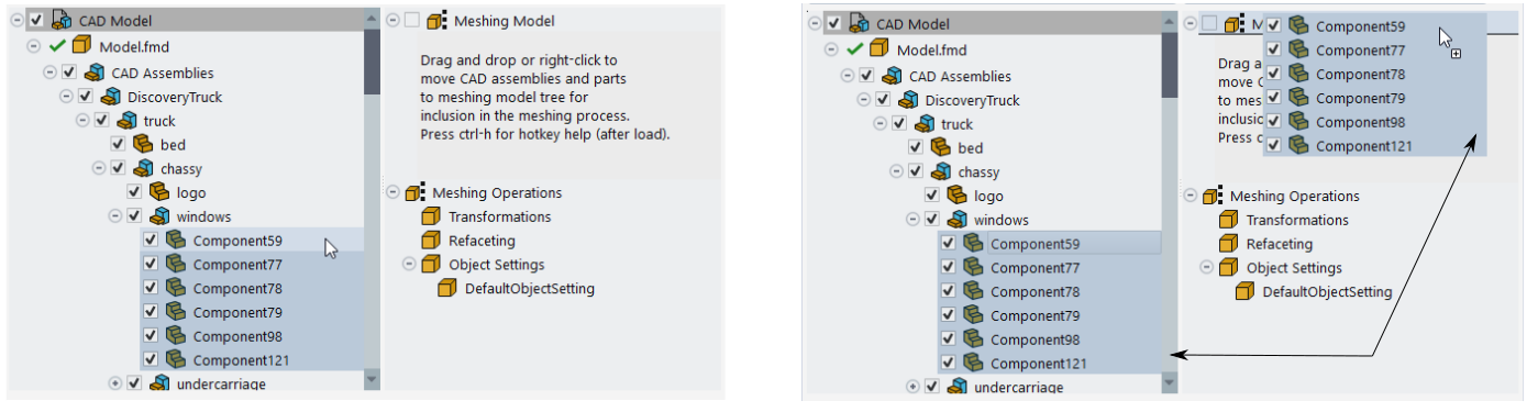
to clear the filer text and return the list to its original state.Select and move objects from the CAD Model tree and place them in the Meshing Model tree:
Drag and drop components from the CAD Model tree onto the Meshing Model tree on the right.
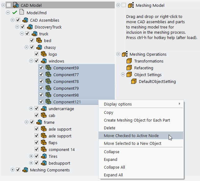
Alternatively, identify one or more part(s) - by enabling the corresponding check box(es) - in the CAD Model tree, right-click and select Move Checked to Active Node in the context menu, so that all of the graphically visible objects are moved to active node
Alternatively, you can use the use the tree's filter and/or wildcard expressions along with the Move button to selectively choose items from the CAD Model tree and move them to the active node in the Meshing Model tree.
Select the object(s) directly in the graphics window, and use the Ctrl+middle-click mouse button combination to move them from the CAD Model tree to the Meshing Model tree.
Selecting an object directly in the graphics window also selects the corresponding object in the tree. You need to right-click an object to select it in the graphics window. Use Ctrl+right-click to select multiple objects in the graphics window, thereby selecting the corresponding objects in the tree.
As items are moved from the CAD Model tree, they are hidden in the CAD Model tree and made visible in the Meshing Model tree. You can toggle the visibility of moved objects altogether by using the Hide Transferred Objects (or the Show Transferred Objects) CAD Model context menu option. If you mistakenly add a component to the Meshing Model tree, you can easily remove it using the Restore to CAD Model option from the context menu, thereby adding it back to the CAD Model tree.
If the CAD Model tree is active, you can visualize the checked CAD objects by clicking the Show CAD Model button.
Various features are available from the context menu of the CAD Model tree, depending on what is selected, including:
Use the Display Options menu to access related sub-options, such as
Use the Display Options > Add to Display option to visualize the selected items from the CAD Model tree in the graphics window. You can select one or more items in the tree and display them. Using a similar Add to Display option in the Meshing Model tree, you can also simultaneously visualize Meshing model objects along side CAD Model objects.
Use the Display Options > Display option to display only the selected items in the graphics window.
Note: You can only display objects using either the CAD Model tree or the Meshing Model tree, but not both.
At the top-level node of the CAD tree, use the Hide Transferred Objects option to hide the visibility of CAD Model tree objects that have been transferred to the Meshing Model tree. Likewise, use the Show Transferred Objects option to expose the visibility of CAD Model tree objects that have been transferred to the Meshing Model tree.
Use the Copy option to copy the selected object to be pasted to another object in the Meshing Model tree.
Use the Create Meshing Object for Each Part option to automatically create a part for the selected object and move it to the Meshing Model tree.
Use the Delete option to remove the selected items from the CAD Model tree.
Use the Move Checked to Active Node option to automatically move the checked object to the active node in the Meshing Model tree.
Alternatively, you can use the use the tree's filter and/or wildcard expressions along with the Move button to selectively choose items from the CAD Model tree and move them to the active node in the Meshing Model tree.
Use the Move Selected to New Object option to be able to easily transfer the selected CAD model object(s) onto another object in the Meshing Model tree.
Note that if only a selected child object is moved, then the moved object is renamed according to the body name.
Use the Collapse All or Collapse options to close all or a portion of the tree.
Use the Expand All or Expand options to open all or a portion of the tree.
The Meshing Model tree is primarily populated with selective parts from your CAD model. The components in the Meshing Model tree will be the pieces of your CAD model that you want to include in your Fluent simulation. They will ultimately become meshing objects, and visible as such, in the Outline View in your Fluent session.
Objects in the Meshing Model tree can be top-level meshing objects (
),
assemblies ( ), or
parts ( ). You
can only have three levels in the tree.When the top node of the Meshing Model tree is selected, use the context menu to Collapse/Expand and/or Collapse All/Expand All of the nodes of the tree, as well as to Sort by Name.
New objects in the Meshing Model tree can indicate their status as either 'update-required' with a lightning bolt icon (
) or as
'up-to-date' with a green check mark icon ( ). When you later update the
task and create and update your meshing objects, the status of any out-of-date object(s)
changes to an 'up-to-date' status in the tree. For geometries with many parts and
assemblies, access to a more granular object status allows Fluent to save time and
resources by only having to update selective portions of the geometry.Select meshing objects directly in the tree in order to perform various tasks. Use Ctrl+left-click to select multiple non-sequential objects in the tree. Use Shift+left-click to select multiple sequential objects in the tree. See Using Hot Key Shortcuts in the Model Trees and the Graphics Window for additional selection and display shortcuts for this task.
Note: An object is highlighted when it is selected in the tree. The check box for an object is used for displaying that object in the graphics window.
Alternatively, you can right-click the object directly in the graphics window, and it will become selected in the corresponding tree. Use Ctrl+right-click to select multiple objects in the graphics window, thereby selecting multiple objects in the tree.
Display a meshing object in the graphics window by enabling the check box (
) to the
left of object in the tree. Likewise, to hide an object from view in the graphics
window, disable the check box. Selecting/deselecting a parent assembly node in the tree
to show/hide the geometry in the graphics window allows for all of its component parts
to also be shown/hidden. Use the Filter Text field to perform name-based searching and filtering on models containing a large number of components.
Enter text into the Filter Text field to see the results instantly. Click the 'x' icon (
)
to clear the filer text and return the list to its original state.Set various properties for selected meshing objects (
,
 ,
,
 , or
, or
 ). See
Setting Properties for Meshing Model Objects for
details.
). See
Setting Properties for Meshing Model Objects for
details.If the Meshing Model tree is active, you can visualize the checked meshing objects by using the Show Meshing Model button at the bottom of the task.
Note that you can manually organize your Meshing Model tree by dragging portions of the tree and dropping them onto other portions of the tree. For instance, you can drag Meshing Model objects and drop them into various Meshing Operations (transformations, refacets and object settings) in order to more easily define your meshing operations.
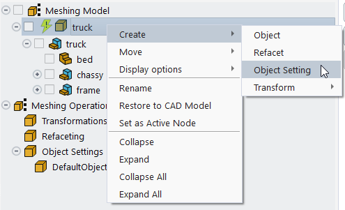
Various features are available from the context menu of the Meshing Model tree, depending on where in the hierarchy you are located, including:
Use the Create option to access related sub-options, such as
Use the Create > Object option to add a generic object to the tree.
By default the Meshing Model tree is empty, however, using the Create > Object option from the context menu, you can create your own custom collection of object categories, where you can add components from the CAD Model tree. Once created, you can save that collection of simulation meshing objects using the Save Meshing Objects icon (
 ) where you can save the object collection in a
 .mmtfile. If you need to use that collection of objects again, you can use the Load Meshing Objects icon ( ) and locate a previously saved
 .mmtfile.The
*.mmtobject collection files include the version number of the current release (for example, for the 2024 R2, release, the files are internally designated with"version": "24.2".You can also use the Select a template drop-down field above the tree to choose an available template of objects, such as External Flow, which contains a template of object categories specific to typical external flow objects.
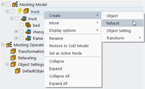
Use the Create > Refacet option to define refaceting operations for the selected component(s). A refacet operation appears in the Meshing Operations tree (with a default name such as
Refacet-1). Expand the Refaceting properties (below the tree) to assign specific properties to the refaceting operation. See Performing Refaceting Operations on Meshing Model Objects for more details.Use the Create > Object Setting option to define object setting operations for the selected component(s). A object setting operation appears in the Meshing Operations tree (with a default name such as
ObjectSetting-1). Expand the Object Settings properties (below the tree) to assign specific properties to the objects setting operation. See Performing Object Setting Operations on Meshing Model Objects for more details.Use the Create > Transform option to specify transformational operations (such as translation, rotation, scaling, etc.) for the selected component(s). A corresponding transform operation appears in the Meshing Operations tree (with a default name such as
Translate-1) where you can expand the transformation properties (below the tree) to assign specific properties to the particular transformation. See Performing Transformation Operations on Meshing Model Objects for more details.
Use the Move option to access related sub-options, such as
Use the Move > Move to a New Object option to relocate the selected component(s). to a new meshing object in the Meshing Model tree where you can move it and rename it accordingly.
Use the Move > Move to a New Sub-object option to relocate the selected component(s). to a new meshing object in the Meshing Model tree where it is a new sub-object of a new parent of the same name.
Use the Cut option to remove an object from the Meshing Model tree where you can then paste it back into the same tree at a different location.
Use the Display Options menu to access related sub-options, such as
Use the Display Options > Add to Display option to visualize the selected items from the Meshing Model tree in the graphics window. You can select one or more items in the tree and display them. Using a similar Add to Display option in the CAD Model tree, you can also simultaneously visualize CAD model objects along side Meshing Model objects.
Use the Display Options > Display option to display only the selected items in the graphics window.
Note: You can only display objects using either the CAD Model tree or the Meshing Model tree, but not both.
If an object has any meshing operations associated with it, use the List Meshing Operations option to list those meshing operations in the console window. See Listing Meshing Operations for more information.
Use the Rename option to assign a new name for the selected object in the tree.
Use the Restore to CAD Model option to remove the selected item from the tree and restore it in the CAD Model tree.
Use the Set as Active Node option to specify the current node as the active node. The active node's label is indicated in bold. When a node is selected as the active node, you are able to transfer checked CAD model objects more easily to the active node using the context menu.
Use the Collapse All or Collapse options to close all or a portion of the tree.
Use the Expand All or Expand options to open all or a portion of the tree.
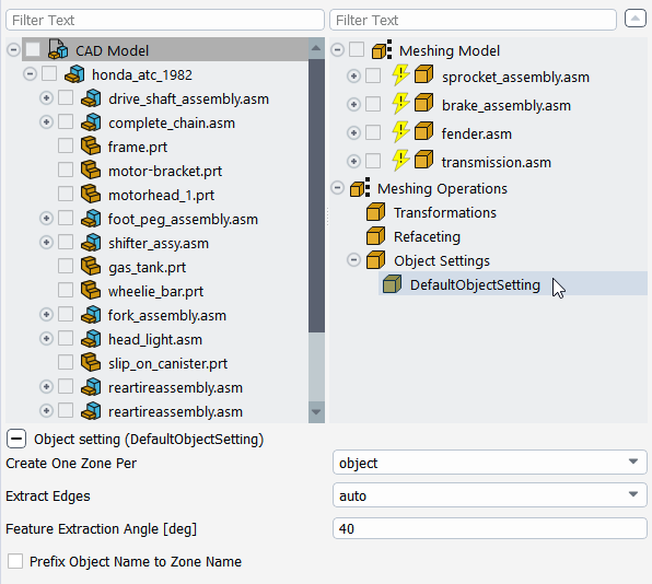
Meshing model objects listed in the tree have various properties that you can set, if necessary. Options vary depending on whether you are creating meshing objects automatically based on parts, or whether you are performing a custom meshing object creation.
By setting the Create Meshing Objects field to One per part, you can automatically create meshing objects based on the individual parts of your imported CAD geometry.
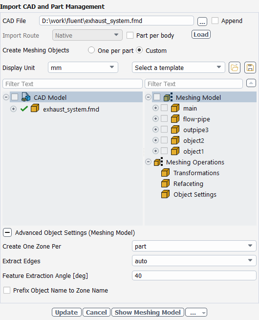
Prior to creating the per-part meshing objects, you can access various CAD geometry properties under Advanced CAD Options.
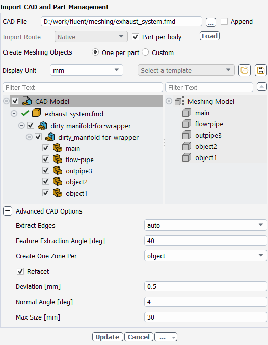
Use the Extract Edges field to determine how edges will be extracted from the CAD geometry (auto, yes, or no). Setting this option to auto will extract edges from the CAD geometry when the number of meshing objects is less than 10,000. If the number of meshing objects exceeds this limit, then no edges are extracted. When this option is set to yes, then edges are extracted regardless of the number of meshing objects. No edges are extracted when this option is set to no.
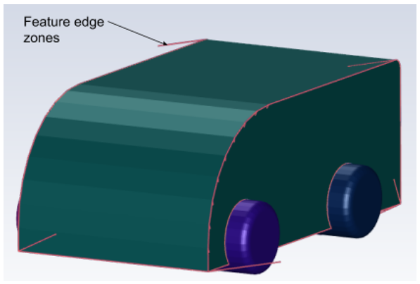
When extracting edges, specify a value for the Feature Extraction Angle field, or use the default value of 40 degrees, to specify the angle at which features will be extracted from the CAD model on import. See Faceting Considerations for details.
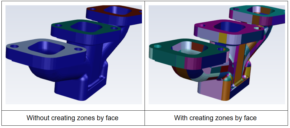
Set the Create One Zone Per option to object, part, body, or face, accordingly. For instance, if face is selected, each CAD surface or face will be assigned to a face zone.
When creating meshing objects by part, use the Refacet check box to enable or disable additional faceting refinement in this task. When enabled, you can change the faceting of the selected object. Only the faceted CAD model is used during the meshing process. In either case, when disabled, normal CAD faceting is performed as defined by the imported CAD file(s).
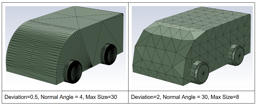
The Deviation controls how far facet edges are away from the model.
The Normal Angle also controls how far facet edges are away from the model. Decreasing the normal angle will result in more facets along the curved edges.
The Max Size controls the maximum size of the facets after the deviation and the normal angle are respected.
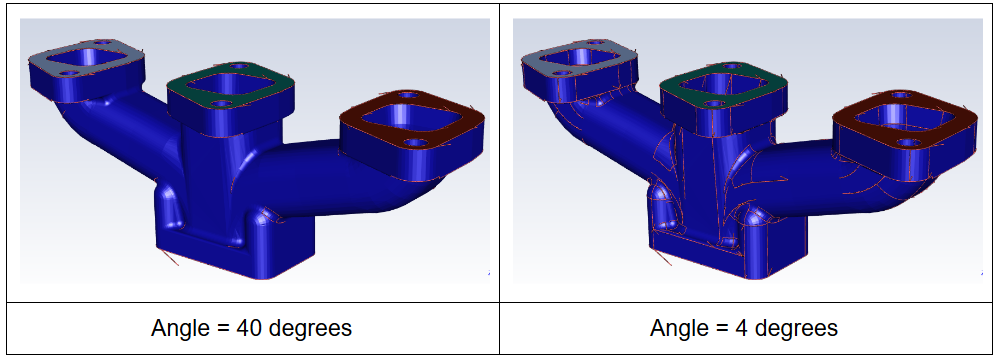
In the following example, the left-hand model uses small values for the deviation and the normal angle in order to capture the curved surface, and a large value for the maximum size in order to get larger facets on the flat surface. The right-hand model uses larger values for the deviation and the normal angle in order to capture the curved surface coarsely, and a smaller value for the maximum size in order to capture the flat surface evenly.
By setting the Create Meshing Objects field to Custom, you can customize the creation of your meshing objects, and selectively choose various properties, transformations, and refaceting options, for any portion of your imported CAD geometry.
Properties for custom meshing objects are available under Advanced Object Settings.
Set the Create One Zone Per option to object, part, body, or face, accordingly. For instance, if face is selected, each CAD surface or face will be assigned to a face zone.
Use the Extract Edges field to determine how edges will be extracted from the CAD geometry (auto, yes, or no). Setting this option to auto will extract edges from the CAD geometry when the number of meshing objects is less than 10,000. If the number of meshing objects exceeds this limit, then no edges are extracted. When this option is set to yes, then edges are extracted regardless of the number of meshing objects. No edges are extracted when this option is set to no.
When extracting edges, specify a value for the Feature Extraction Angle field, or use the default value of 40 degrees, to specify the angle at which features will be extracted from the CAD model on import. See Faceting Considerations for details.
Enable or disable the Prefix Object Name to Zone Name accordingly. Enabling this allows for naming the corresponding face zone using the object name as a prefix. This option is available only for custom meshing object creation.
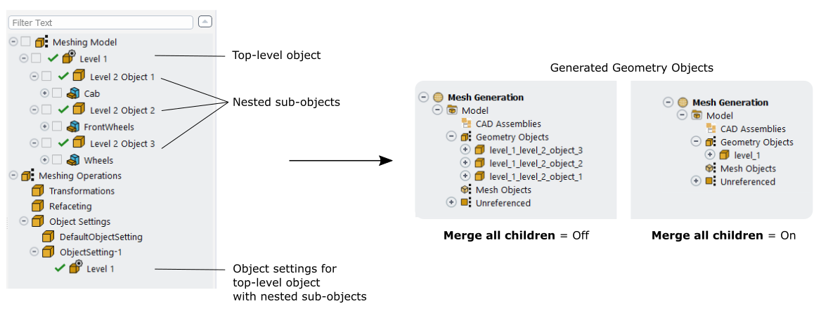
Enable or disable the Merge all children accordingly. This option is only available when there are nested objects in the Meshing Model tree, and you want to assign object property settings to the top-level object. Upon updating the task, disabling this option ensures that each nested sub-object becomes its own geometry object, whereas enabling this option merges all child sub-objects into a single geometry object.
Enable or disable the Use default settings for sub-objects accordingly. This option is only available when there are nested objects in the Meshing Model tree, and you want to assign object property settings to the top-level object. Upon updating the task, enabling this option applies the top-level (or the default) object settings to all child sub-objects, whereas disabling this option lets you define separate object settings for your individual sub-objects.
Note: Use the … menu button at the bottom of the task, and
select the Save FMD option to save your changes in a new
.fmd file for future use. This is especially useful for
particularly large, complicated models in which you have made many specialized changes
to the properties (such as refaceting), and allows for a faster load time. Note that
mirrored components cannot be saved to the .fmd format.
You can perform specific operations on one or more meshing model object(s). The operations are grouped together at the bottom of the Meshing Model tree.
Note: To remove all meshing operations at once, right-click the Meshing Operations node of the Meshing Model tree and select Delete All from the context menu.
Likewise, to update all meshing operations at once, right-click the Meshing Operations node of the Meshing Model tree and select Update All from the context menu.
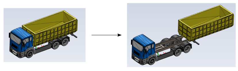
After you have imported the original CAD model, there may be times when you need to slightly adjust or alter the geometry. You can make such modifications (such as simple Cartesian-based rotational and translational operations) on selected portions of your meshing model, prior to creating the meshing objects based on your imported CAD geometry.
Note: When capturing transformation operations in journal files, be aware that any unused translation and/or rotation input(s) will be recorded even if the transform type is changed prior to applying the transformation operation.
To create a transformation for a meshing model component, select one or more components from the Meshing Model tree,
and use the
context menu option to select a transformational
operation (such as translation, rotation, scaling, etc.) for the selected component(s). A
corresponding transform operation appears in the Meshing Operations tree (under
Transformations) with a corresponding default name
(Translate-1 for example). Any transformations you define are
collected under Meshing Operations and can be performed alone, or
combined with each others in a particular sequence if desired. Transformations are updated
when the meshing objects are created with this task.
In addition, you can use the context menu to Delete, Add to Display, Display, or Rename a transformation operation.
You can
identify objects in the tree that have operations (such as transformations) applied to
them since they will have a distinct icon (![]() or
or ![]() , or
, or ![]() ).
).
You can create as many different transformations as you need. For a selected transformation object, use the context menu to perform other general operations such as renaming, deleting, etc.
Note: To remove all meshing transformation operations at once, right-click on the Transformations node under the Meshing Operations node of the Meshing Model tree and select Delete All from the context menu.
Likewise, to update all meshing transformation operations at once, right-click on the Transformations node under the Meshing Operations node of the Meshing Model tree and select Update All from the context menu.
To create a translational transformation for a meshing model component, select one or more components from the Meshing Model tree, and choose Translate in the Create Transform context menu where you can then change the following properties:
Assign the as either or Global.
The local coordinate system is one that is associated with the individual CAD geometry as it is being created, where one chooses to re-orient that CAD sketch and create the model. Its orientation can vary based on its placement in an assembly of the entire model (for example, tires for a car). The global coordinate system has a fixed orientation, whereas the local coordinate system will have a different orientation. If, however, the CAD part was created without changing the coordinate systems, then there will be no difference between the local and global coordinate systems.
Use the Translate field to specify a translational transformation. Enter an appropriate value (in the display units) in the X, Y, and/or Z direction, based on the specified coordinate system.
Click Apply Transform to see the results of your settings. Likewise, click Undo Transform to return to the original orientation.
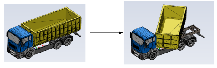
To create a rotational transformation for a meshing model component, select one or more components from the Meshing Model tree, and choose Rotate in the Create Transform context menu where you can then change the following properties:
Assign the as either or Global.
The local coordinate system is one that is associated with the individual CAD geometry as it is being created, where one chooses to re-orient that CAD sketch and create the model. Its orientation can vary based on its placement in an assembly of the entire model (for example, tires for a car). The global coordinate system has a fixed orientation, whereas the local coordinate system will have a different orientation. If, however, the CAD part was created without changing the coordinate systems, then there will be no difference between the local and global coordinate systems.
Use the Rotate field to specify a rotational transformation. Enter an appropriate value (in degrees) around the X, Y, and/or Z axis, based on the specified coordinate system.
Click Apply Transform to see the results of your settings. Likewise, click Undo Transform to return to the original orientation.
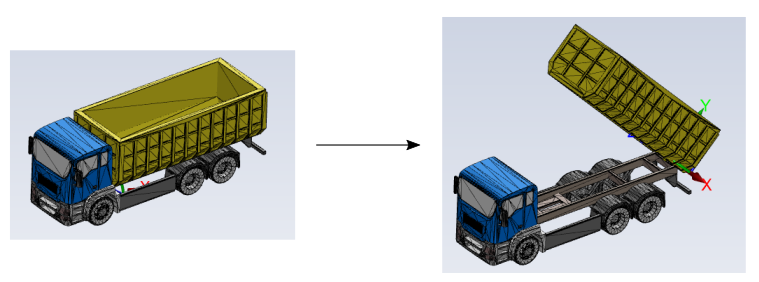
To create an axial rotational transformation for a meshing model component, select one or more components from the Meshing Model tree, and choose Rotate About Axis in the Create Transform context menu where you can then change the following properties:
Assign the as either or Global.
The local coordinate system is one that is associated with the individual CAD geometry as it is being created, where one chooses to re-orient that CAD sketch and create the model. Its orientation can vary based on its placement in an assembly of the entire model (for example, tires for a car). The global coordinate system has a fixed orientation, whereas the local coordinate system will have a different orientation. If, however, the CAD part was created without changing the coordinate systems, then there will be no difference between the local and global coordinate systems.
Use the Angle field to specify a rotational angle (in degrees) of transformation.
Specify the Pivot point of the rotation using an appropriate value for X, Y, and/or Z, based on the specified coordinate system.
Specify the Axis components values for the X, Y, and/or Z
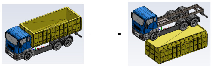
Figure 4.9: Transformation Example: Truck Bed Rotation of 45 Degrees With a Global Pivot in X About the Z Axis
Click Apply Transform to see the results of your settings. Likewise, click Undo Transform to return to the original orientation.
To create a scaling transformation for a meshing model component, select one or more components from the Meshing Model tree, and choose Scaling in the Create Transform context menu where you can then change the following properties:
Assign the as either or Global.
The local coordinate system is one that is associated with the individual CAD geometry as it is being created, where one chooses to re-orient that CAD sketch and create the model. Its orientation can vary based on its placement in an assembly of the entire model (for example, tires for a car). The global coordinate system has a fixed orientation, whereas the local coordinate system will have a different orientation. If, however, the CAD part was created without changing the coordinate systems, then there will be no difference between the local and global coordinate systems.
Use the Scale factor field to specify a factor to scale the part size. Enter an appropriate value around the X, Y, and/or Z axis, based on the specified coordinate system.
Click Apply Transform to see the results of your settings. Likewise, click Undo Transform to return to the original orientation.
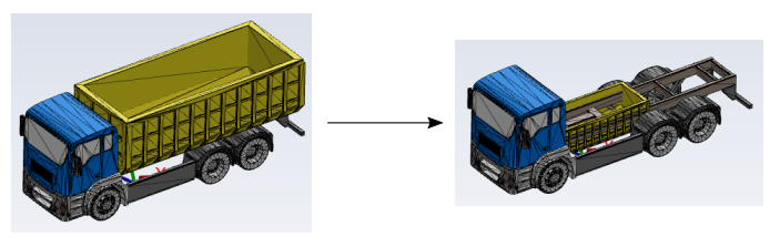
To create a mirroring transformation for a meshing model component, select one or more components from the Meshing Model tree, and choose Mirror in the Create Transform context menu where you can then change the following properties:
Assign the as either or Global.
The local coordinate system is one that is associated with the individual CAD geometry as it is being created, where one chooses to re-orient that CAD sketch and create the model. Its orientation can vary based on its placement in an assembly of the entire model (for example, tires for a car). The global coordinate system has a fixed orientation, whereas the local coordinate system will have a different orientation. If, however, the CAD part was created without changing the coordinate systems, then there will be no difference between the local and global coordinate systems.
Use the Mirror about field to specify the mirroring plane as either the XY plane, the YZ plane, or the XZ plane, based on the specified coordinate system.
Click Apply Transform to see the results of your settings. Likewise, click Undo Transform to return to the original orientation.
You can perform additional faceting refinement for selected customized meshing object(s) by applying individual refaceting operations. Refaceting will refacet the original CAD geometry. Only the faceted CAD model is used during the meshing process. When refaceting operations are not used, normal CAD faceting is performed as defined by the imported CAD file(s). See Faceting Considerations for details.
To create a refaceting operation for a meshing model component:
Select one or more components from the Meshing Model tree.
Use the context menu option to create a refacet operation for the selected component(s). A refacet operation appears in the Meshing Operations tree (under Refaceting) with the default name of
Refacet-1.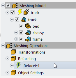
You can use the context menu to Delete, Add to Display, Display, or Rename a refacet operation.
You can identify objects in the tree that have operations (such as refaceting) applied to them since they will have a distinct icon (
or , or ). You can create as many different refaceting operations as you need. For a selected object, use the context menu to perform other general operations such as renaming, deleting, etc.
Select
Refacet-1and expand the Refaceting properties (the +/- icon below the tree) to assign specific properties to the refaceting operation.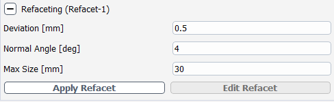
The Deviation controls how far facet edges are away from the model.
The Normal Angle also controls how far facet edges are away from the model. Decreasing the normal angle will result in more facets along the curved edges.
The Max Size controls the maximum size of the facets after the deviation and the normal angle are respected.
Click Apply Refacet to see the results of your settings and to preview changes to the refaceting settings in the graphics window while you are still within the task.
In the following example, the left-hand model uses small values for the deviation and the normal angle in order to capture the curved surface, and a large value for the maximum size in order to get larger facets on the flat surface. The right-hand model uses larger values for the deviation and the normal angle in order to capture the curved surface coarsely, and a smaller value for the maximum size in order to capture the flat surface evenly.
Refaceting will refacet the original CAD geometry. Only the faceted CAD model is used during the meshing process. In either case, when disabled, normal CAD faceting is performed as defined by the imported CAD file(s).
Click Edit Refacet to return to a state where you can change values and repeat as needed for as many objects in the tree as required.
Note: To remove all meshing refaceting operations at once, right-click on the Refaceting node under the Meshing Operations node of the Meshing Model tree and select Delete All from the context menu.
Likewise, to update all meshing refaceting operations at once, right-click on the Refaceting node under the Meshing Operations node of the Meshing Model tree and select Update All from the context menu.
You can perform basic object property settings on multiple meshing model objects all at once (properties such as zone assignment, edge extraction, feature extraction angle, etc. as described in Creating Customized Meshing Objects).
To create a object setting operation for a meshing model component:
Select one or more components from the Meshing Model tree.
Alternatively, you can select the assembly's parent node in the tree if you want to apply the same object settings to all of its children.
Use the context menu option to create a object setting operation for the selected component(s). An object setting operation appears in the Meshing Operations tree (under Object Settings) with the default name of
ObjectSetting-1.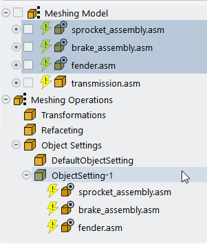
You can use the context menu to Delete, Add to Display, Display, or Rename one or more selected object settings. The Add to Display option allows you to visualize one or more selected object settings from the Meshing Model tree in the graphics window.
You can identify objects in the tree that have operations (such as object settings) applied to them since they will have a distinct icon (
or , or ). You can create as many different object setting operations as you need. For a selected object, use the context menu to perform other general operations such as renaming, deleting, etc.
Note: As part of the Object Settings, the DefaultObjectSetting node is available if you want to specify and apply a common set of object properties to several meshing objects at the same time.
The DefaultObjectSetting node is only for editing its properties to apply them to one or more other meshing objects, and cannot be renamed or removed.
Select
ObjectSetting-1and expand the Object Settings properties (the +/- icon below the tree) to assign specific properties to the object setting operation.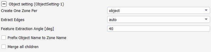
Any of the provided properties can be set and applied to all of the selected parts in the Meshing Model tree using a single object setting. Properties of meshing objects from previous mesh files read into the workflow can still be edited under Advanced Object Settings. The available properties are described in Creating Customized Meshing Objects.
If an object has any meshing operations associated with it, use the List Meshing Operations option to list those meshing operations in the console window.
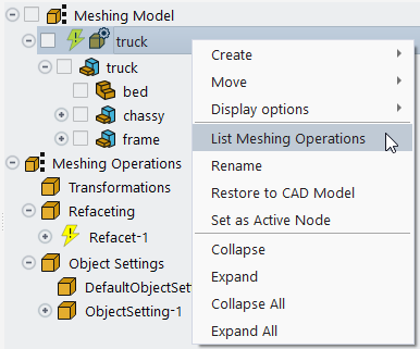
The following is an example of output to the console window:
Meshing operations on meshing object: bed are as follows:
Transformations: (Transform-1)
Refaceting: Refacet-2
Faceting is very important for many reasons: if the faceting is too coarse, you will lose fidelity; if the faceting is too fine, then you will not capture important features in rounds or fillets.
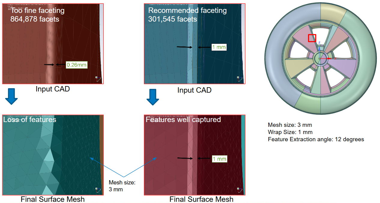
Here the minimum facet edge in the fillet is roughly the same size as the minimum local size control to be used. Once feature edges are extracted using 12 degrees, you will have:
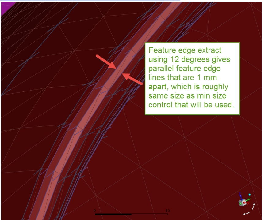
This will lead to faster graphics operation (due to lighter model), faster meshing, and better feature capturing. Even if the target size becomes larger (not more than 2 times), it will still respect those feature lines, leading to anisotropic mesh, and reduced cell count.
To change how different components are colored and displayed in the graphics window, use the … menu button at the bottom of the task, and select Display Options.
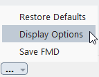
This displays the Display Options dialog:
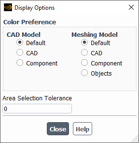
The Display Options dialog allow you to select color preferences for the displayed components of the CAD Model tree or the Meshing Model tree. Options include to color by Default (automatic), by CAD, by Component, or by Objects. You can also provide an Area Selection Tolerance.
In addition to the hot key shortcuts that are available in Fluent in meshing mode (Appendix C: Shortcut Keys), the following selection and display hot key shortcuts are available in the Import CAD and Part Management task:
| Action | Keys | |
|---|---|---|
| Selection Tools | Select component instances | Ctrl+I |
| Select parent assembly | Ctrl+P | |
| Clear selections | f2 | |
| Clear CAD Model tree selections | Ctrl+Y | |
| Display Mode Tools | Preview the other display mode | Ctrl+J |
| Disable the preview of the other display mode | Ctrl+K | |
| Toggle between the preview of the other display mode | Ctrl+L | |
| Display Tools | Show all | Ctrl+Shift+A |
| Show/hide edges | Ctrl+Shift+E | |
| Hide | Ctrl+Shift+H | |
| Isolate | Ctrl+Shift+I | |
| Miscellaneous Tools | Compute distance | Ctrl+D |
| Print this help | Ctrl+H | |
| Position filter | Ctrl+X | |
| Toggle right mouse button | f3 | |
| Toggle selection method | f4 | |
| Auto scale | Ctrl+A | |
| CAD object filter | Ctrl+B | |
| Move selected component(s) into a new object in the Meshing Model tree, | Alt+M |