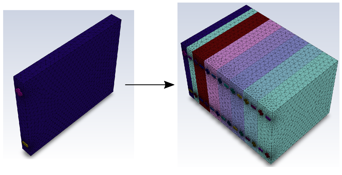
Using the Add Linear Mesh Pattern task, you can create linear patterns of objects based on one or more CAD parts. This capability can greatly simplify meshing for CAD geometries that require multiple, linearly spaced parts such as in modeling batteries, for example.
Note: This task must be added after the Generate the Surface Mesh task and before the Describe Geometry task. In certain situations, however, objects that need to be selected to perform mesh pattern operations are merged at the end of surface meshing. To avoid this, the Add Linear Mesh Pattern task needs to be inserted into the workflow prior to executing the Generate the Surface Mesh task.
Provide a Name for the new mesh pattern, or use the default name.
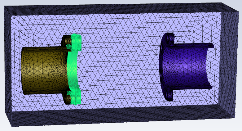
Select the object(s) in the list from which you want to create a mesh pattern. The selected part(s) will be highlighted in the graphics window.
Use the Filter Text option in the drop-down to provide text and/or regular expressions in filtering the list (for example, using *, ?, and []). You can also choose the Use Wildcard option in the drop-down to provide wildcard expressions in filtering the list. When you use either
?or*in your expression, the matching list item(s) are automatically selected in the list. Use^,|, and&in your expression to indicate boolean operations for NOT, OR, and AND, respectively. See Filtering Lists and Using Wildcards for more information.For the Estimate Both Axis and Pitch field, indicate whether or not you want Fluent to provide a best approximation of the pattern's axis direction and the displacement of the pattern's objects (pitch), or whether you want to estimate the Pitch Only (default).
Note: This estimation only takes place once, either when the object is selected, or when the option is changed.
For the Axis Direction, specify a normalized value for X-Component, Y-Component, and Z-Component of the direction of the pattern's axis.
Specify the Pitch, or displacement factor, that defines the spacing between the pieces, or units, of the pattern.
Specify the Total Number of Units to indicate the overall number of units in the pattern you wish to create.
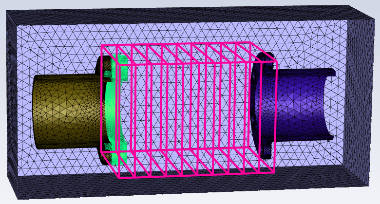
Click Preview Pattern to see a preview of the pattern in the graphics window, based on the specifications provided. The preview will only consist of an outline of the proposed number of units, their axis direction and their spacing. If necessary, make adjustments to the pattern axis definition, pitch, etc., and click the Preview Pattern button again as needed.
Use the Highlight Unit Alignment? field to add graphical highlights to the interfaces between the pattern units so that you can more easily inspect the final pattern for proper alignment. The highlights are visible once the mesh pattern is added. Misaligned units can cause a failure in the share topology of the battery cells.
For the Invoke Custom Numbering or Pattern? field, select yes to expose additional fields regarding how repeated cells are numbered and labelled as meshing objects. For instance, repeated cells in battery models follow a specific naming process, and these fields ensure proper naming of the repeated units.
Specify a value for the First Unit First Number field. This value will be appended to the end of the name of the first unit's meshing object.
Specify a value for the First Unit Second Number field. This value will also be appended to the end of the name of the first unit's meshing object (and be incremented accordingly), and dictates the labelling for the pattern's meshing objects.
Note: The names generated for the meshing objects that are created using the designated pattern are dependent on what you assign for the First Unit First Number and the First Unit Second Number fields (if greater than 1). For instance, the naming convention is useful when modeling batteries with various groupings of battery cells. Fluent internally calculates the number of repeating cells based on these two numbers.
For example, if a selected part named
cellparthas the First Unit First Number value set to1, and the First Unit Second Number is set to1, then that means there is a single battery cell in the unit the name of the first unit in the pattern will becellpart_1. Subsequent unit names are incremented by one (the First Unit Second Number) to becellpart_2,cellpart_3, etc.). If, however, the First Unit Second Number is set to something other than 1, such as4for example, then that means there are four battery cells in the unit and the name of the first unit in the pattern will start withcellpart_1and another suffix will be appended and incremented by the First Unit Second Number to becellpart_1-4. Subsequent units in the pattern will then have names incremented accordingly, and be calledcellpart_5-8,cellpart_9-12, etc.).For Use Custom Pattern? field, select yes if you want to apply your own custom pattern in the entry field below, The syntax for describing a pattern is discussed in Creating Custom Patterns Using Scripts.
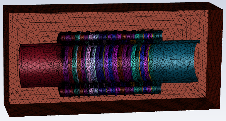
Click Add Linear Mesh Pattern. The mesh pattern will appear in the graphics window.
If you need to make adjustments to any of your settings in this task, click Revert and Edit, make your changes and click Update, or click Cancel to cancel your changes.
Note: To ensure that the units of the mesh pattern are properly connected, you must also use a Shared Topology task in your workflow (see Applying Share Topology).
Note: Additional linear mesh patterns cannot be created based on objects that have already been used in an existing mesh pattern.
Once you are satisfied with your changes, proceed to the next step in the workflow.
Custom patterns can be generated in the Add Linear Mesh Pattern task by using a specialized scripting syntax. A single pattern can easily be constructed with a few commands. Multiple patterns can also be combined together easily and performed at one time. In either case, the commands can be copied and pasted into the text window in the Add Linear Mesh Pattern task.
There are two main approaches for creating a custom pattern:
Singular Pattern - where a single naming convention is applied to all objects. This assumes that the unit already has a pattern indicative of a "word-number" pattern (such as a single word followed by a single number, for example,
Cell1). With each copy, the number is incremented and a '0" is inserted (for example,Cell01,Cell02,Cell03, etc.). Within this pattern type, there are two rules governing naming: regular (default) and explicit.Use the explicit approach where only a single copy is created with a designated prefix. The command simply copies zones with the
name1prefix to thename2prefix. For example,one-,two-,three-, etc. You can combine explicit patterns with regular patterns. You can also have multiple explicit pattern commands before you start using regular commands.Dual Pattern - where a dual naming convention is applied to two sets of objects. This assumes that the units already have a pattern indicative of a "word-number-word-number" prefix (for example
C1P1,C1P2, etc.). With each copy, the first number is incremented (for example,C1P1-C1P2,C2P1-C2P2,C3P1-C3P2, etc.). Within this pattern type, there are two rules governing naming: regular (default) and flip.Use the flip name rule to flip prefixes names between each objects at each copy. This is often needed if the copy includes a 180 degree rotation.
The syntax for a custom pattern is as follows. See Examples of Creating Custom Patterns Using Scripts for more information.
<number-of-operations> (<name1> <name1-value>)
                              (<name2> <name1-value>)
                              (<number1> <number1-value>)
                              (<number2> <number1-value>)
                              (rotation-axis (x-value y-value z-value))
                              (rotation-angle (x-value y-value z-value))
                              (translation-vector (x-value y-value z-value))
                              (pitch <pitch-value>)
                              (namerule <namerule-value>)
                              (type <type-value>)
                              (copies <number-of-copies>)
end
where
- number-of-operations
The number of operations that make up the pattern.
- name1
The first name designation.
- number1
The first number designation, set to
1by default.- name2
The second name designation, depending on the context. When using a singular pattern (with the
explicitname rule) this is the prefix of the copy. When using a dual pattern, this is the second name of the prefix.- number2
The second number designation, depending on the context. When using a singular pattern, this is the increment of
number1. When using a dual pattern, this is the second number in the prefix. By default, this is set to1.- rotation-axis
The rotational axis setting (if any), set to
(0 1 0)by default. For example, use "rotation-axis (0 0 1)" to indicate that the pattern's copies will rotate along the Z-axis.- rotation-angle
The rotational angle setting (if any), set to
0by default, in degrees. For example, use "rotation-angle 45" to indicate that the pattern's copies will rotate 45 degrees.- translation-vector
The translational vector setting (if any), set to
(0 0
              1)
by default. For example, use "translation-vector (1 0 0)" to indicate that the pattern's copies will be translated in the (relative) X direction. When (pitch 0), then you would specify the absolute translation in X, Y, or Z.- pitch
The pitch setting (if any), set to
0by default. For example, use "pitch 20" to indicate that the displacement factor between a pattern's copies will be 20.- namerule
The name rule change (if any), set to
regularby default.For a singular pattern, you can choose from
regular(default) orexplicit. Use theexplicitname rule to use explicit naming.For a dual pattern, you can choose from
regular(default) orflippattern. Use theflipname rule to flip prefixes names between each objects at each copy. This is often needed if the copy includes a 180 degree rotation.- number-of-operations
The number of operational elements contained in the first pattern.
- type
The pattern type designation (if any), set to
singleby default. For example, use "type dual" to indicate that the pattern will use the dual pattern approach (where a dual naming convention is applied to two sets of objects). The type can also besingle(the default value) indicating a single naming convention is applied to all objects.- copies
The number of copies created. For example, use "
copies
                  5
" to indicate that the pattern will be composed of 5 copies.
Important: You should keep the following rules in mind when using this syntax:
The number of operations must be the first number specified in the pattern definition. The order of the remaining keyname-value pairs is not important.
Each pattern definition (or copy) must be on its own individual line.
The pattern definition only needs to include keyname-value pairs that are changing.
In most cases, the most recent copy is used to create the next copy.
Using the most recent copy as the starting point, you can perform a sequential series of copy operation combinations (e.g., first-second, second-third, third-fourth, etc.), however, you cannot make the second copy in the sequence based on the first copy (e.g., first-second, first-third, first-fourth, etc.).
The exception is when the
explicitname rule is used in combination with theregularname rule). Note that you can also have more than one explicit name rule pattern commands before you start using regular name rule commands.
See Examples of Creating Custom Patterns Using Scripts for more information.
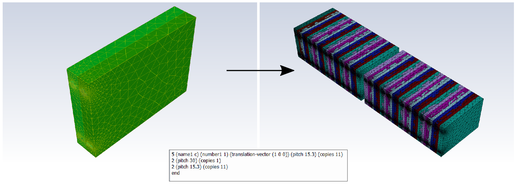
Multiple patterns can be included at once and copied and pasted into the text field of the task. For instance, the following is an example of three custom patterns you can define at one time:
5 (name1 c) (number1 1) (translation-vector (1 0 0)) (pitch 15.3) (copies 8) 2 (pitch 30) (copies 1) 2 (rotation-angle 180) (copies 3) end
In this case, the first pattern has a total of 5 commands designating
name1, number1, the
translation-vector value, the pitch
value, and the number of copies.
5 (name1 c) (number1 1) (translation-vector (1 0 0)) (pitch 15.3) (copies 8)
The second pattern has a total of two commands designating the
pitch value and providing a singular copy.
2 (pitch 30) (copies 1)
The third pattern has a total of two commands designating the
rotation-angle as 180 degrees and creating three
copies.
2 (rotation-angle 180) (copies 3)
The series of patterns is completed using the end
statement.
In the case where you are only interested in creating a series of sequential copies,
use the explicit name rule. In this case, only sequential
copying is allowed and automatically handled, such that name1 =
name2 from the previous custom pattern.
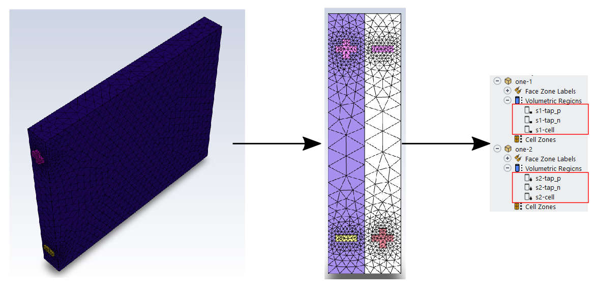
For instance, if you originally have a geometry of a battery cell with three components:
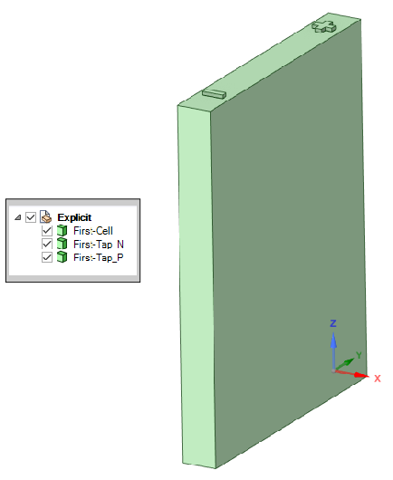
If you wanted to make a series of sequential battery cells using a custom mesh pattern, for example, you could use something similar to the following using explicit naming:
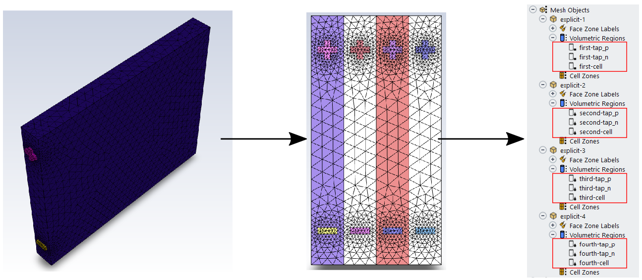
6 (name1 first) (name2 second) (translation-vector (1 0 0)) (pitch 10) (namerule explicit) (copies 1) 2 (name2 third) (copies 1) 2 (name2 fourth) (copies 1) end
The first line calls for making a copy of the three sub-components, replacing the prefix "first" with "second" in their names, and applying a translation and a pitch. The second line creates another copy based on the first copy, replacing the prefix "first" with "third". The third line creates yet another copy of the first pattern, replacing the prefix "first" with "fourth" in the name. When the entire pattern is applied within the workflow task, you get four sequential copies, each with their unique prefixes based on the naming of the first set of sub-components.
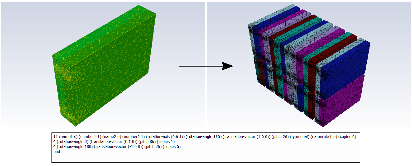
The following is an example of using explicit naming with a regular singular pattern approach.
Similar to the previous example, if you originally have a geometry of a battery cell with three components:

If you wanted to make a series of sequential, alternating battery cells using a custom mesh pattern, for example, you could use something similar to the following using explicit and regular naming pattern:
8 (name1 s1) (name2 s2) (translation-vector (1 0 0)) (pitch 10) (rotation-angle 180) (rotation-axis (0 0 1)) (copies 1) (namerule explicit) 7 (name1 s) (number1 1) (number2 2) (rotation-angle 0) (pitch 20) (namerule regular) (copies 6) 2 (number1 2) (copies 6) end
The first line calls for making a copy of the three sub-components, replacing the prefix "s1" with "s2" in their names, and applying a translation, a rotation, and a pitch.
The second line creates six additional copies based on the first pattern's
translation and incrementing the prefix by two (e.g., from s01
to s03, s05,
s07, etc.).
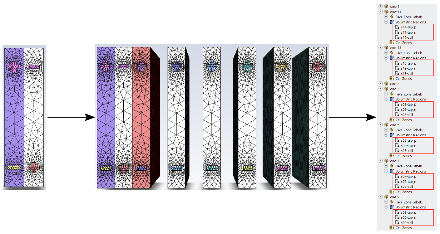
The third line creates another six copies of the first pattern's second cell
translation and increments the prefix by two (e.g., from s02 to
s04, s06,
s08, etc.).
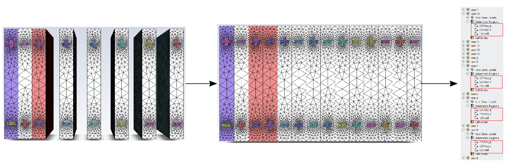
When the entire pattern is applied within the workflow task, you get a collection of seven sequential, alternating sets of battery cells, each with their unique prefixes based on the naming of the first set of sub-components.