


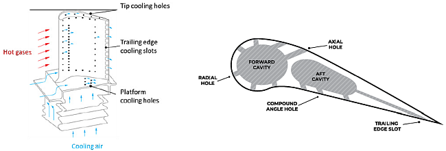
The cooling of the turbine blades within a gas turbine engine is usually achieved via the film-cooling approach. This is where cool gas is injected into the boundary layer of the flow over the blade from lots of small holes on its surface. This presents a problem for CFD modeling, as it can be both difficult and time-consuming to create and mesh a geometry which adequately resolves all the holes.
Within Ansys Fluent, you can easily create models for Blade Film Cooling (BFC) using the Boundary Interface feature. This involves taking a standard blade model setup, and creating virtual holes on an existing boundary mesh. The holes can then be treated as an inlet or outlet, and with the associated boundary condition settings, the simulation can be solved in the usual way. The holes can also be moved, or have their size and shape changed, without the need for costly remeshing.
The steps for setting up blade film cooling are discussed in the following sections:
Steps for creating a virtual Boundary Interface to perform Blade Film Cooling are outlined below:
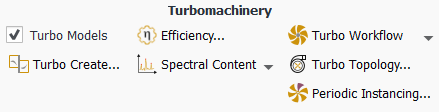
Enable Turbo Models for the domain.
Once enabled, Boundary Interfaces appears in the outline view.
Import hole center locations from a profile in
.csvformat. See Profiles for details.Each data row in the profile represents an individual hole (x,y,z coordinates) and additional columns can be used to provide flow data for each hole. The Interpolation Method should remain the default constant.
The Reference Frame specified for the profile controls how the hole positions behave during the simulation. For steady cases, the frame should be set to
global. For transient cases, the chosen reference frame depends on the motion of the cell zone to which the holes are connected.If the cell zone is stationary (for example, a stator row), then the Reference Frame should be set to
global.If the cell zone is moving (for example, a rotor), then selecting
globalfor Reference Frame keeps the holes stationary as the rotor moves past them. Such an arrangement would be appropriate for shroud cooling. However, if the holes are intended to cool the moving rotor blade, then the Reference Frame should be set such that it that tracks the rotor Cell Zone (for details on creating a Reference Frame, see Creating and Using Reference Frames). In this configuration, the holes will be stationary within the rotating frame and move position with the rotor.
Note: The hole coordinates do not have to be defined precisely on the mesh surface, and a tolerance is used to locate the holes on the boundary. However, if the hole location is too far from the surface, it will not be located and is ignored.
An example of a hole definition profile is shown below:
[Name]
Rotor Pressure Surface Cooling

[Parameters]
InjectionTemperature = 420 [K]
MyParameter = 333 [s^-1]
MyParameter2 = 44.44 []
Diameter = 3.4 [mm]

[Spatial Fields]
x	 y	 z

[Data]			     Velocity in Stn  Velocity in Stn  Velocity in Stn   Mass Flow Some Variable  Sector
x [m]	 y [m]     z [m]   Frame u [m s^-1] Frame v [m s^-1] Frame w [m s^-1]  [kg s^-1]  [kg s^-1]     Tag []
-2.50E-01  1.08E-03  2.22E-01     2.63E+01        -9.87E+01	  5.09E+01	 3.71E-04     12.12         1
-2.61E-01  1.06E-03  2.22E-01     1.08E+01        -1.03E+02	  5.32E+01	 3.71E-04     12.12         1
-2.72E-01  1.04E-03  2.22E-01    -6.59E+00        -1.06E+02	  4.60E+01	 3.71E-04     12.12         1
-2.83E-01  1.03E-03  2.22E-01    -2.97E+01        -1.10E+02	  4.41E+01	 3.71E-04     12.12         1
-2.94E-01  1.01E-03  2.22E-01     2.07E+00        -1.12E+02	  3.32E+01	 3.87E-04     12.12         1
#-- End of profile Rotor Pressure Surface Cooling--

[Name]
Rotor Suction Surface Cooling

[Parameters]
InjectionTemperature = 420 [K]
MyParameter = 333 [s^-1]
MyParameter2 = 44.44 []
Diameter = 3.4 [mm]

[Spatial Fields]
x	 y	 z

[Data]			     Velocity in Stn  Velocity in Stn  Velocity in Stn   Mass Flow Some Variable  Sector
x [m]	 y [m]     z [m]   Frame u [m s^-1] Frame v [m s^-1] Frame w [m s^-1]  [kg s^-1]  [kg s^-1]     Tag []
-2.97E-01  -1.22E-03  2.25E-01     2.63E+01        -9.87E+01	  5.09E+01	 3.71E-04     12.12         1
-2.86E-01  -1.24E-03  2.22E-01     1.08E+01        -1.03E+02	  5.32E+01	 3.71E-04     12.12         1
-2.75E-01  -1.26E-03  2.22E-01    -6.59E+00        -1.06E+02	  4.60E+01	 3.71E-04     12.12         1
-2.63E-01  -1.29E-03  2.22E-01    -2.97E+01        -1.10E+02	  4.41E+01	 3.71E-04     12.12         1
-2.52E-01  -1.32E-03  2.22E-01     2.07E+00        -1.12E+02	  3.32E+01	 3.87E-04     12.12         1
#-- End of profile Rotor Pressure Surface Cooling--
Note: Multiple hole definition profiles can included in one
.csvfile as shown in the example.Create a virtual geometry to represent the holes from the Create/Edit Boundary Geometry dialog box.
 Setup
→ Boundary
Interfaces
Setup
→ Boundary
Interfaces Create/Edit
Geometry
Create/Edit
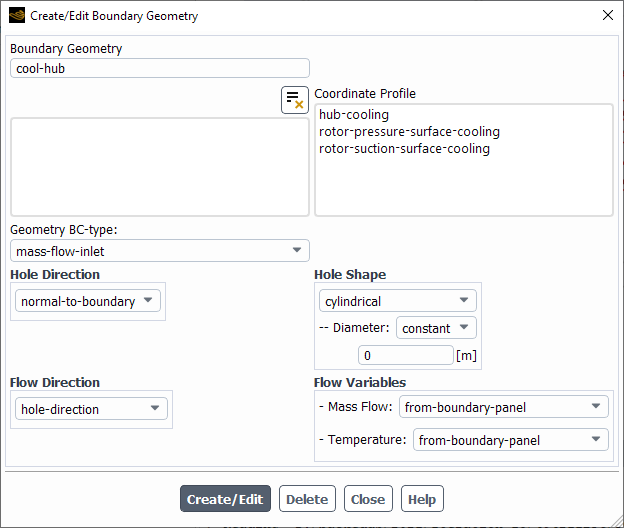
GeometryUnder Boundary Geometry, enter a name for the virtual hole geometry.
Under Coordinate Profile, select a profile to define the hole center locations. The hole center profile must be defined in
.csvfile format.Under Geometry BC-type, select the type of boundary for the holes. The options are
mass-flow-inlet,mass-flow-outlet,pressure-inlet, orwall. In most cases for blade film cooling, you will specify the holes as mass flow inlets, although for a bleed you would require an outlet.Under Hole Direction Specification, select one of the following options:
The holes are oriented normal to the surface based on their location.
The holes are oriented by specifying a X, Y, and Z Direction Component. Using a
constantdirection component orients all holes in the same direction. If you want individual holes to be oriented in different directions, selectprofileand choose the appropriate Profile Variable to assign the direction components for each individual hole based on data from the profile. You can also select a profile Parameter which will apply the constant value to a Direction Component for all holes.The holes are oriented by specifying a Radial, Tangential, and Axial Direction Component. The axial direction will be defined by the Reference Frame properties of the parent cell zone. Using a
constantdirection component orients all holes in the same direction. If you want individual holes to be oriented in different directions, selectprofileand choose the appropriate Profile Variable to assign the direction components for each individual hole based on data from the profile. You can also select a profile Parameter which will apply the constant value to a Direction Component for all holes.
Under Flow Direction Specification, you have the option of specifying the flow direction independently from the hole direction. You have the following options:
hole-directionThe flow is aligned with the hole direction.
from-boundary-panelThe flow direction is taken from the overlap boundary condition specification. For details, see Specifying Overlap Boundary Conditions.
normal-to-boundaryThe flow is oriented normal to the surface regardless of hole direction.
cartesianThe flow is oriented by specifying a X, Y, and Z Component of Flow. Using a
constantComponent of Flow orients the flow in the same direction for each hole. If you want individual holes to have different flow directions, selectprofileand choose the appropriate Profile Variable to assign the flow direction for each individual hole based on data from the profile. You can also select a profile Parameter which will apply the constant value to a Component of Flow for all holes.cylindricalThe flow is oriented by specifying a Radial, Tangential, and Axial Component of Flow. The axial direction will be defined by the Reference Frame properties of the parent cell zone. Using a
constantComponent of Flow orients the flow in the same direction for each hole. If you want individual holes to have different flow directions, selectprofileand choose the appropriate Profile Variable to assign the flow direction for each individual hole based on data from the profile. You can also select a profile Parameter which will apply the constant value to a Component of Flow for all holes.
Under Hole Shape, select
cylindricalorrectangleand specify the relevant dimensions.For cylindrical holes, specify the Diameter as
constantif each hole is the same size or selectprofileand choose the appropriate Profile Variable to assign the diameter for each individual hole based on data from the profile. You can also select a profile Parameter which will apply the constant value to all holes.For rectangular holes, specify the Length and Width as
constantif each hole is the same size or selectprofileand choose the appropriate Profile Variable to assign the width or length for each individual hole based on data from the profile. You can also select a profile Parameter which will apply the constant value to all holes.
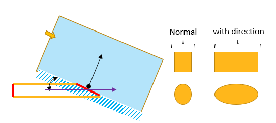
Note: For both cylindrical and rectangular hole shapes, the orientation of the hole is based on the projection of the specified hole direction onto the local underlying boundary surface. If the specified hole direction is not normal to the boundary, then the hole shape is modified to account for this as if the hole were "drilled" into the boundary in the specified direction. As such, a cylindrical hole definition can result in an elliptical shape on the boundary, and similarly a rectangle defined with equal width and length can result in a non-square hole, as shown in Figure 14.20: Hole Shape Dependency from Hole Direction.
Under Flow Variables, there exist additional settings depending on the physics present in the simulation. If Energy is enabled, and the Geometry BC-type is an inlet or wall, then a Temperature specification is required. If the Geometry BC-type is an inlet or an outlet, then a Mass Flow rate or Total Pressure specification is required.
For Mass Flow, the following options are available:
from-boundary-panelThe mass flow is taken from the overlap boundary condition specification. For details, see Specifying Overlap Boundary Conditions.
profileIf you want individual holes to have different mass flow rates, select
profileand choose the appropriate Profile Variable to assign the mass flow rate for each individual hole based on data from the profile. You can also select a profile Parameter which will apply the constant value to all holes.constant-per-holeA single value for the mass flow rate is applied to each hole.
total-mass-flowThis value corresponds to the total mass flow for all the located holes, which is distributed equally between those holes.
total-for-all-sectorsThis value corresponds to the total mass flow of all the located holes, assuming a full 360 degree wheel were being modeled. The specified mass flow is distributed proportionately to any modeled sectors, and then equally between the holes within those sectors.
For Temperature, the following options are available:
from-boundary-panelThe temperature is taken from the overlap boundary condition specification. For details, see Specifying Overlap Boundary Conditions.
profileIf you want individual holes to have different temperatures, select
profileand choose the appropriate Profile Variable to assign the temperature for each individual hole based on data from the profile. You can also select a profile Parameter which will apply the constant value to all holes.radial-distributionAllows for a temperature variation within each individual hole. The temperature for each face within a hole is defined by the equation:

(14–14)
Where A and B are user-defined constants and
 is the Reference Temperature, which can be defined as
constantunder Reference Value or selectprofileto use hole-specific values for Reference Temperature as defined from the input profile.The resultant temperature variation is quadratic, based on the radial position of the hole face centers from the input hole center, compared to the input hole radius. The value of k is evaluated automatically by Fluent, to ensure the enthalpy flux for each hole is approximately the same as if the hole were specified with a uniform temperature equal to the Reference Temperature. This helps to reduce the sensitivity of the model to the mesh resolution of the holes themselves.
For a pressure-inlet, a Total Pressure and Loss Coefficient specification is required.
For total pressure, the following options are available:
from-boundary-panelThe total pressure is taken from the overlap boundary condition specification. For details, see Specifying Overlap Boundary Conditions.
profileIf you want individual holes to have different total pressure specifications, select
profileand choose the appropriate Profile Variable to assign the total pressure for each individual hole based on data from the profile. You can also select a profile Parameter which will apply the constant value to all holes.
The Loss Coefficient reproduces the pressure head loss due to the hole drilling itself. For details on the loss coefficient, see Specifying the Loss Coefficient. The following options are available:
from-boundary-panelThe loss coefficient is taken from the overlap boundary condition specification. For details, see Specifying Overlap Boundary Conditions.
constantA single, constant value is applied to all holes.
factor-and-length-ratioTwo further values are required for an internal calculation of the loss coefficient. Both are constant for all holes: A Darcy Friction Factor and an assumed Length-to-Diameter Ratio for the hole drilling.
Once fully defined, click Create/Edit. Note that existing geometry definitions can be modified and you can define multiple geometries if needed. It is often useful to group holes into separate geometries according to their location: for example, blade pressure side, blade suction side, hub, shroud, and so on.
After the hole geometry has been defined, you must create the Boundary Interface between the geometry and an existing boundary. To do this, right-click Boundary Interfaces in the outline view and select New to open the Create/Edit Boundary Interfaces dialog box.
![]() Setup → Boundary
Interfaces
Setup → Boundary
Interfaces![]() New
New
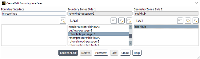
Under Boundary Zones Side 1, select the boundary that the holes will be located on.
Under Geometry Zones Side 2, select the boundary geometry that was created in Specifying the Virtual Hole Geometry.
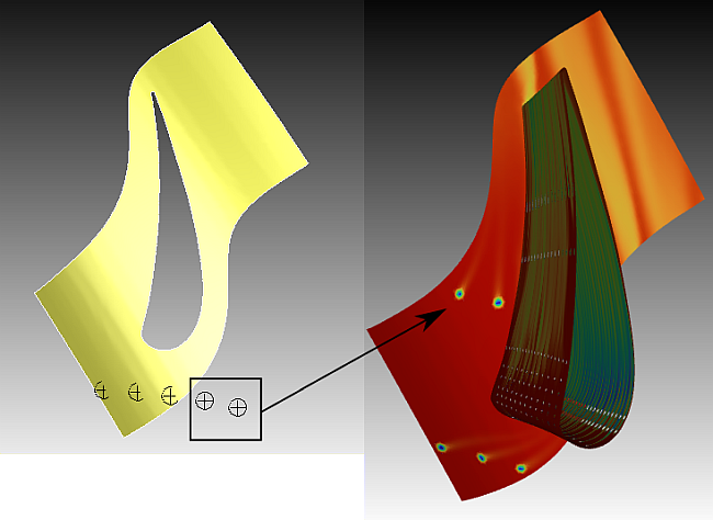
Click Preview and the selected Boundary Zones will be displayed, along with symbols indicating the proposed locations of the holes as implied by the selected Geometry Zones.
Note that the symbols do not indicate the actual size and shape of the holes; they are only markers. The default symbols and colors are used but these can be changed using the following console command for each Geometry:
/define/virtual-boundary/hole-geometry/edit/[geometry-name]/preview.Click Create/Edit and the boundary interface will appear in the list. You can also select previous defined boundary interfaces to edit or delete.
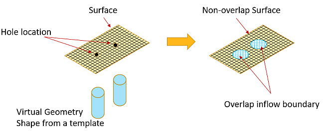
Once created, Fluent intersects the selected boundaries with the selected geometries, resulting in one overlap boundary for each geometry and separate non-overlap boundaries for each of the underlying boundary zone locations, as shown in Figure 14.21: Creation of Overlap and Non-overlap Surfaces. The new overlap boundaries will automatically be created as mass-flow inlets or outlets, or an inlet vent (for pressure), depending on the type defined within the geometry.
Note: If a profile option, or any option other than
constant or from-boundary-panel is
selected for Flow Direction Specification or within Flow
Variables for the relevant Geometry Zone, then Fluent
creates a special internal profile that is only valid for this overlap boundary. It has a
name beginning with vbr and also contains the overlap boundary
name. Fluent then assigns this internal profile to the relevant boundary conditions on
the overlap boundary, corresponding to the Boundary Geometry specification. The internal
profile will not be visible or usable anywhere but on the appropriate overlap
boundary.
In the configuration where you have a rotationally periodic model with hole locations specified for a Boundary Zone that fall outside of that Boundary Zone and the periodic boundaries, then Fluent will attempt to rotate the hole locations until they overlap with the Boundary Zone as shown in Figure 14.22: Holes Outside the Parent Cell Zone Rotated to Overlap with Mesh
This is triggered automatically when a Boundary Interface is created using a Boundary Zone that is attached to a parent Cell Zone that has an axis vector defined and at least on rotationally periodic interface pair. Any hole locations specified within the Boundary Geometry that are not initially overlapping with the parent Cell Zone mesh will be rotated (using the pitch angle defined by the periodic pair) until they do overlap. This rotation moves the hole location from just outside one periodic boundary, to just inside the other periodic boundary, as if it were located in an adjacent passage. If, even after successive rotation, the hole cannot be located within the mesh, then that hole will remain undefined.
This automated feature is designed to lower the sensitivity of the positioning of the rotationally periodic boundary pairs, in relation to hole locations.
Additionally, if a hole is large enough to touch or cross one of the periodic boundaries, then the portion of the hole outside that boundary will be transformed so that it appears inside the other periodic boundary. The complete hole will then appear to span the periodic pair.
After a Boundary Interface has been created, you can expand its entry in the outline view to see all of the components that make up that boundary interface.
![]() Setup → Boundary
Interfaces → [Name]
Setup → Boundary
Interfaces → [Name]
In this example, expanding the Boundary Interface int-cool-hub
reveals the following:
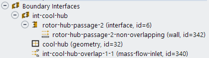
Boundary zone (
rotor-hub-passage-2)Non-overlap zone (
rotor-hub-passage-2-non-overlapping)Geometry (
cool-hub)Overlap zone (
int-cool-hub-overlap-1-1)
You can right-click the overlap or non-overlap zone and select Display to view the zone in the graphics viewer. The non-overlap zone displays the non-intersected faces and the overlap zone displays the intersected mesh, revealing the exact hole shapes and sizes.
Once the Boundary Interface is created, you may need to specify additional boundary conditions at the new overlap boundary.
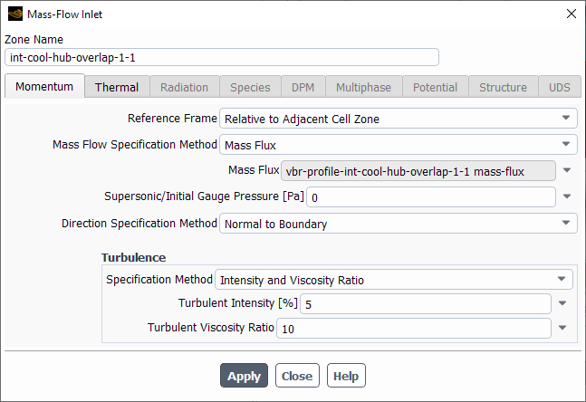
The boundary type will already be set based on the original geometry definition (Mass-Flow Inlet, Mass-Flow Outlet, or Wall).
The overlap boundary will have some of its options automatically set by Fluent, depending on the associated Boundary Geometry specification. For example, if you selected
profileorconstant-per-holefor the relevant Boundary Geometry, then Fluent will automatically assign the relevant internal profile to the Mass Flux specification. However, if thefrom-boundary-paneloption is chosen then you must manually specify the mass flow (or mass flux) directly. This value then corresponds to the total mass flow for all the located holes which is then distributed between those holes based on area-weighting.Verify the flow direction for each hole. The Direction Specification Method, Coordinate System, and the Flow Direction components should all have been set automatically according to the Boundary Geometry specification. Note that if Fluent has not set these options, and instead you specify the flow direction components as constant values, then each hole will have the same flow direction.
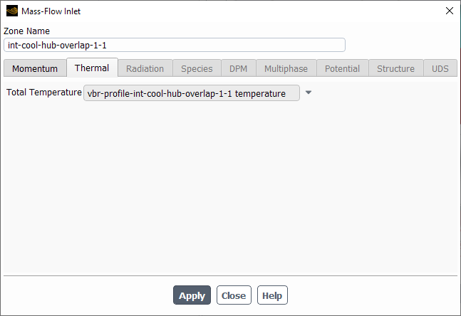
Set appropriate values for other inflow quantities, where necessary, such as turbulence or temperature (shown below). For a quantity such as temperature, hole-specific data can be used by selecting the
profileoption for Temperature on the relevant Boundary Geometry, and choosing an additional data column from the original geometry definition profile.Important: You are still able to manually edit the overlap Boundary Condition and change any automatically generated settings. However, this can lead to inconsistency with the Boundary Geometry specification. It is generally recommended that you change any overlap Boundary Condition indirectly by editing the relevant geometry (see Specifying the Virtual Hole Geometry).
Only available for boundaries, and not volumes. Flow injection is supported at a Boundary Interface only, which must refer to an existing boundary definition.
Holes must have their size and shape defined such that they do not overlap with another hole.
Hole centers must be located within, or close to, a Cell Zone mesh. If any are not, then a warning will be printed that those holes will not be included and they will not contribute to fluid flow.
Flow boundary conditions are currently specified as constant for each hole, and cannot vary across an individual hole.
Reported boundary fluxes will show the specified mass flow for each hole overlap boundary, as well as the total mass flow for all geometries intersecting the original underlying boundary. However, the Net Results will not include this duplication and should still tend to zero across all boundaries for a converged solution.
When modeling Blade Film Cooling on a moving rotor blade in a transient simulation, where the Boundary Interface Geometry references a profile defined in a local reference frame rotating with the rotor, an incorrect Mass Flow will be applied to the holes unless the
from-boundary-paneloption has been chosen for Mass Flow on the geometry. Also, Fluent may become unstable if the rotation angle becomes greater than one pitch.Even if the
from-boundary-paneloption has been selected, the hole positions may not be updated correctly with the rotor position if more than one Boundary Interface is defined.