


In supersonic and hypersonic flows, temperature can rise significantly due to a shock wave or viscous heating of a solid surface. To prevent the vehicle surface from melting, certain Thermal Protection Systems (TPS) must be applied. One common practice is to coat the surface with a layer of an ablative material. During vehicle's operation, the ablative material is chipped away due to surface reactions that remove a significant amount of heat and keep the surface temperature below the melting point. As the ablative process changes the surface contour (geometry), it has a significant effect on aerodynamics of the flow field, particularly on super and hypersonic flows. The ablation model in Ansys Fluent considers not only the heat and mass transfer associated with the surface reaction but also the dynamic mesh movement associated with the geometry change of the surface.
Note: Additional feature license is required to enable the use of this model. Please contact your Ansys representative to check for the availability of the license increment.
The following ablation models are available in Ansys Fluent:
Vielle’s model
The Vielle’s model [6] is based on the empirical formulation that calculates the ablative surface recessing rate
 (m/s) as:
(17–11)
where
 is the absolute pressure, and
  and
and  are user-specified parameters.
The Vielle’s model considers the effects of the ablative process on the computational domain, namely the aerodynamic response of the surface. The Vielle’s model can also be used to consider mass and heat transfer of the ablative process. Based on the ablative material density
 and the species composition (mass fractions
  ), Ansys Fluent computes the injected mass flux
  for species
  as follows:
(17–12)
Surface reaction model
This model considers the surface reaction that occurs on the ablative surface. As a result, mass transfer and heat transfer on the ablative surface are accounted for. The ablative surface recession rate
 (m/s) is calculated as:
(17–13)
where
 is the density of the ablative material, and
  is the surface etching rate. The surface etching rate
  equals the negative surface deposition rate
  in Equation 7–83 in the Fluent Theory Guide.
The surface recession rate computed by the ablation models is then used to determine the mesh movement velocity.
Note that the ablation model is available only for transient simulations.
The basic steps for using the ablation condition at the wall are listed below. Note that only steps that are pertinent to the ablation model are shown.
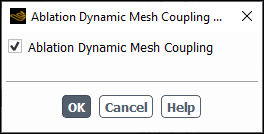
Enable Ablation Dynamic Mesh Coupling in the Ablation Dynamic Mesh Coupling Model dialog box.
 Setup → Models
→ Ablation
Setup → Models
→ Ablation  Edit...
When the Ablation Dynamic Mesh Coupling is enabled, the Ablation tab will appear in the Wall dialog box.
If you want to consider surface reactions on the walls, enable the following:
In the Species Model dialog box, enable the Species Transport model and Wall Surface (Reactions group box).
Setup → Models
→ Species
Edit...For each wall where you want to use the ablation surface reaction condition, enable Reaction in the Wall dialog box (Species tab). Note that if you are setting up ablation between a fluid and solid zone, the Reaction option must be enabled on the fluid side of the coupled wall.
For each wall where you want to apply the ablation model, select an appropriate option from the Ablation Model drop-down list in the Wall dialog box (Ablation tab); note that if you are setting up ablation between a fluid and solid zone, the Ablation Model must be selected on the fluid side of the coupled wall. You can use one of the following options:
none (default): Signifies that this wall boundary is not an ablative surface.
Vielle’s model: Calculates the ablative surface recessing rate
 using Equation 17–11. You
need to specify the following Vielle’s model parameters:
using Equation 17–11. You
need to specify the following Vielle’s model parameters:Parameter A: is
in Equation 17–11.Parameter n: is
in Equation 17–11.
If you want to consider mass and heat transfer of the ablative process, enable Species Flux and specify the following:
Ablative Material Density:
 in Equation 17–12
Species Mass Fraction:
 in Equation 17–12
Ansys Fluent will use Equation 17–12 to compute the injected mass flux for each species.
Surface Reaction: Calculates the ablative surface recessing rate
using Equation 17–13. You
need to specify the following parameter:Ablative Material Density: is
in Equation 17–13.
The Surface Reaction model is available only when Wall Surface is enabled in the Species Model dialog box and Reaction is enabled in the Wall dialog box (Species tab).
When either Vielle’s model or Surface Reaction is selected, once you click Apply in the Wall dialog box, Ansys Fluent automatically makes the following changes:
Enables the Dynamic Mesh model
Enables Smoothing and Remeshing in the Mesh Methods group box and enables relevant smoothing and remeshing methods in the Mesh Method Settings dialog box
Creates a dynamic mesh zone with the same name as the wall where the ablation condition is applied and sets Mesh Motion UDF/Profile to **ablation** in the Dynamic Mesh Zones dialog box (Motion Attributes tab)
Note: The dynamic mesh model settings applied by Ansys Fluent might not be ideal for your particular case. You may need to modify these settings to suit your specific needs. For example, if you are setting up ablation on a moving wall between a fluid and solid zone, you must create a deforming zone for the solid zone that uses the radial basis function smoothing method (for details, see Radial Basis Function Smoothing).
It is recommended that you run the calculation in steady-state first, and then enable the ablation model and use the converged steady-state solution as the starting point for transient simulations.