


When a time-accurate solution (rather than a time-averaged solution) for rotor-stator interaction is desired, you must use the sliding mesh model to compute the unsteady flow field. The sliding mesh model is the most accurate method for simulating flows in multiple moving reference frames, but also the most computationally demanding.
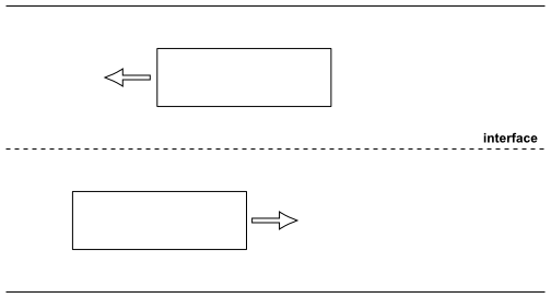
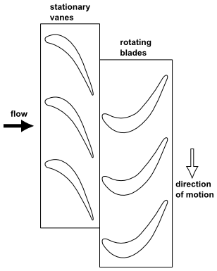
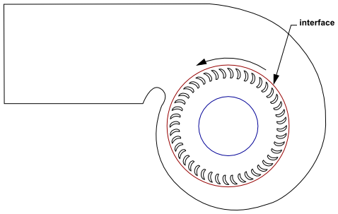
Most often, the unsteady solution that is sought in a sliding mesh simulation is time-periodic. That is, the unsteady solution repeats with a period related to the speeds of the moving domains. However, you can model other types of transients, including translating sliding mesh zones (for example, two cars or trains passing in a tunnel, as shown in Figure 13.1: Two Passing Trains in a Tunnel). Note that the sliding mesh can be modeled using periodic boundaries (Figure 13.2: Rotor-Stator Interaction (Stationary Guide Vanes with Rotating Blades)) or a circular/cylindrical interface (Figure 13.3: Blower).
Note that for flow situations where there is no interaction between stationary and moving parts (for example, when there is only a rotor), it is not necessary to use a sliding mesh, and the moving reference frame model is recommended. (See Flow in a Moving Reference Frame for details.) If you are interested in a steady approximation of the interaction, you may use the multiple reference frame model or the mixing plane model, as described in The Multiple Reference Frame Model and The Mixing Plane Model in the Theory Guide.