In the sliding mesh technique, two or more cell zones are used. (If you generate the mesh in each zone independently, you must merge the mesh files prior to starting the calculation, as described in Reading Multiple Mesh/Case/Data Files in the User’s Guide.) Each cell zone is bounded by at least one “interface zone” where it meets the opposing cell zone. The interface zones of adjacent cell zones are associated with one another to form a “mesh interface.” The two cell zones will move relative to each other along the mesh interface.
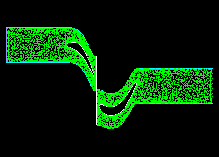
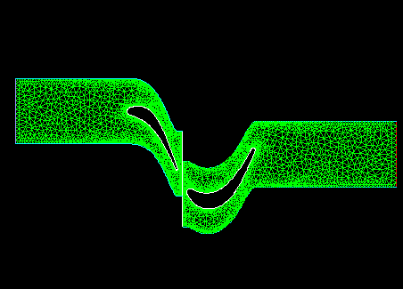
During the calculation, the cell zones slide (that is, rotate or translate) relative to one another along the mesh interface in discrete steps. Figure 13.4: Initial Position of the Meshes and Figure 13.5: Rotor Mesh Slides with Respect to the Stator show the initial position of two meshes and their positions after some translation has occurred. Note that all non-conformal interfaces will be automatically updated (if necessary) by Ansys Fluent when the mesh is updated.
As the rotation or translation takes place, node alignment along the mesh interface is not required. Since the flow is inherently unsteady, a time-dependent solution procedure is required.