Ansys Fluent solves the equations of fluid flow and heat transfer, by default, in a stationary (or inertial) reference frame. However, there are many problems where it is advantageous to solve the equations in a moving (or non-inertial) reference frame. Such problems typically involve moving parts (such as rotating blades, impellers, and similar types of moving surfaces), and it is the flow around these moving parts that is of interest. In most cases, the moving parts render the problem unsteady when viewed from the stationary frame. With a moving reference frame, however, the flow around the moving part can (with certain restrictions) be modeled as a steady-state problem with respect to the moving frame.
Ansys Fluent’s moving reference frame modeling capability allows you to model problems involving moving parts by allowing you to enable moving reference frames in selected cell zones. When a moving reference frame is activated, the equations of motion are modified to incorporate the additional acceleration terms that occur due to the transformation from the stationary to the moving reference frame. By solving these equations in a steady-state manner, the flow around the moving parts can be modeled.
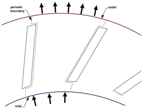
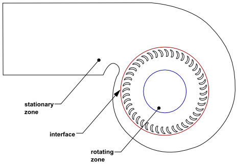
For many problems, it may be possible to refer the entire computational domain to a single moving reference frame. This is known as the single reference frame (or SRF) approach. The use of the SRF approach is possible; provided the geometry meets certain requirements. For more complex geometries, it may not be possible to use a single reference frame. In such cases, you must break up the problem into multiple cell zones, with well-defined interfaces between the zones. This is the multiple reference frame (or MRF) approach and is discussed in The Multiple Reference Frame Model. If unsteady interaction between the stationary and moving parts is important, you can employ the sliding mesh approach to capture the transient behavior of the flow. The sliding meshing model will be discussed in Modeling Flows Using Sliding and Dynamic Meshes.
The principal reason for employing a moving reference frame is to render a problem that is unsteady in the stationary (inertial) frame, steady with respect to the moving frame. For a steadily moving frame (for example, the frame speed is constant), it is possible to transform the equations of fluid motion to the moving frame such that steady-state solutions are possible. By default, Ansys Fluent permits the activation of a moving reference frame with a steady speed. If the speed is not constant, the transformed equations will contain additional terms (see Relative Velocity Formulation in the Theory Guide). It should also be noted that you can run an unsteady simulation in a moving reference frame with constant speed. This would be necessary if you wanted to simulate, for example, vortex shedding from a rotating fan blade. The unsteadiness in this case is due to a natural fluid instability (vortex generation) rather than induced from interaction with a stationary component.
For more information about the equations for moving reference frames, see Equations for a Moving Reference Frame in the Theory Guide.