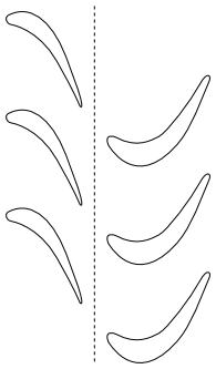
The mesh interface and the associated interface zones can be any shape, provided that the two interface boundaries are based on the same geometry. Figure 13.6: 2D Linear Mesh Interface shows an example with a linear mesh interface and Figure 13.7: 2D Circular-Arc Mesh Interface shows a circular-arc mesh interface. (In both figures, the mesh interface is designated by a dashed line.)
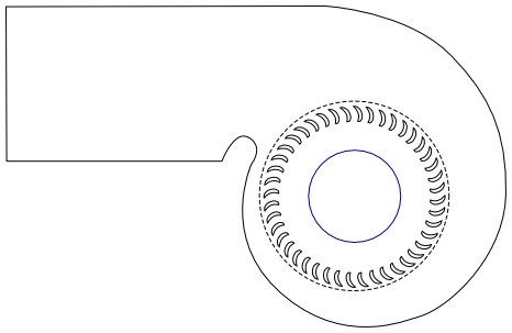
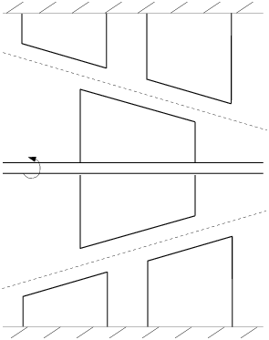
If Figure 13.6: 2D Linear Mesh Interface was extruded to 3D, the resulting sliding interface would be a planar rectangle; if Figure 13.7: 2D Circular-Arc Mesh Interface was extruded to 3D, the resulting interface would be a cylinder. Figure 13.8: 3D Conical Mesh Interface shows an example that would use a conical mesh interface. (The slanted, dashed lines represent the intersection of the conical interface with a 2D plane.)
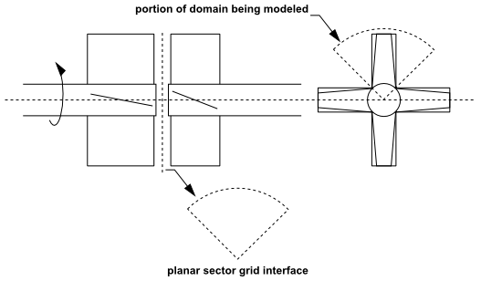
For an axial rotor/stator configuration, in which the rotating and stationary parts are aligned axially instead of being concentric (see Figure 13.9: 3D Planar-Sector Mesh Interface), the interface will be a planar sector. This planar sector is a cross-section of the domain perpendicular to the axis of rotation at a position along the axis between the rotor and the stator.