


The Fuel Cell and Electrolysis module (sometimes referred to as the Resolved Electrolyte module) is provided as an add-on module with the standard Ansys Fluent licensed software.
A fuel cell is an energy conversion device that converts the chemical energy of fuel into electrical energy. With the Fuel Cell and Electrolysis Model, both the triple-phase boundary (TPB), also known as the catalyst layer, and the ionic conducting electrolyte (also known as the membrane in PEMFC terminology) are included in the computational domain. The Fuel Cell and Electrolysis module allows you to model PEMFC, SOFC, and high-temperature electrolysis (or solid oxide electrolyzer cell (SOEC)).
To determine the physical domains that are included in the Fuel Cell and Electrolysis module, a schematic of a polymer electrolyte membrane fuel cell (PEMFC) is shown in Figure 20.3: Schematic of a PEM Fuel Cell.
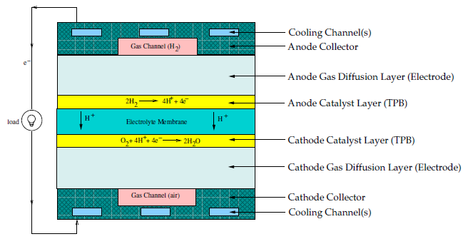
Hydrogen flows into the fuel cell on the anode side. It diffuses through the porous gas diffusion layers and comes in contact with the catalyst layer. Here it forms hydrogen ions and electrons. The hydrogen ions diffuse through the polymer electrolyte membrane at the center, the electrons flow through the gas diffusion layer to the current collectors and into the electric load attached. Electrons enter the cathode side through the current collectors and the gas diffusion layer. At the catalyst layer on the cathode side, the electrons, the hydrogen ions, and the oxygen combine to form water.
In the Fuel Cell and Electrolysis Model in Ansys Fluent, two electric potential fields are solved. One potential is solved in the electrolyte and the TPB catalyst layer. The other is solved in the TPB catalyst layer, the porous electrode, and the current collectors. The rate of electrochemical reactions are computed in the TPB layers at both the anode and the cathode. Based on the cell voltage that you prescribe, the current density value is computed. Alternatively, a cell voltage can be computed based on a prescribed average current density.
For more information, see the following sections:
The proton exchange membrane fuel cell (PEMFC) has emerged as a favored technology for
auto transportation and power generation because it is compact, clean, runs at low temperature
( C), permits an adjustable power output, and can be started relatively
rapidly. Hydrogen is supplied at the anode and air is supplied at the cathode. The following
electrochemical reactions take place in the anode and cathode triple phase boundary (TPB)
layers, respectively,
C), permits an adjustable power output, and can be started relatively
rapidly. Hydrogen is supplied at the anode and air is supplied at the cathode. The following
electrochemical reactions take place in the anode and cathode triple phase boundary (TPB)
layers, respectively,
 | (20–58) |
 | (20–59) |
Electrons produced in the anode travel through an external circuit to the cathode, while
protons ( ) travel through the membrane from the anode TPB to the cathode TPB, thereby
forming an electrical circuit.
) travel through the membrane from the anode TPB to the cathode TPB, thereby
forming an electrical circuit.
As more and more water is generated at the cathode, due to both osmotic drag and electrochemical reactions, water vapor pressure exceeds saturation pressure forming liquid water. The formation and transport of liquid water in the cathode is an important feature that can strongly influence cell performance of a PEMFC.
While the conventional PEMFC operates at low temperatures to keep the water-based membrane humidified for the purpose of allowing proton transport across the electrodes, the high-temperature PEMFC uses mineral acid-based membrane. This type of PEMFC can operate at temperatures well above 100° C. The main advantage of such a device is the elimination of humidifiers since water is present only in gas phase at the high temperature.
Unlike the low-temperature PEMFC, solid oxide fuel cells operate at very high temperatures
( C). Hydrogen is supplied at the anode, either directly or through internal
reforming of another hydrocarbon fuel, and air is supplied at the cathode. The following
electrochemical reactions take place in the anode and cathode triple phase boundary layers,
respectively,
C). Hydrogen is supplied at the anode, either directly or through internal
reforming of another hydrocarbon fuel, and air is supplied at the cathode. The following
electrochemical reactions take place in the anode and cathode triple phase boundary layers,
respectively,
 | (20–60) |
 | (20–61) |
In the cathode TPB, oxygen is reduced to oxygen ions which are then conducted through the ceramic electrolyte to the anode TPB where they react with hydrogen to form water and release electrons. The electrons travel through an external circuit to a load and then back to the cathode to close the circuit.
There has been an increasingly strong need for the large-scale production of hydrogen as a secondary energy carrier. One of the cleaner and more efficient methods of producing hydrogen is to use high-temperature electrolysis (also called solid oxide electrolyzer cell (SOEC)) to split water molecules. Therefore, electrolysis is essentially a reversed fuel cell process. Power is supplied to an electrolyzer to convert water vapor into hydrogen and oxygen. Water vapor is fed through the anode electrodes to the active electrolyte region. The following electrochemical reactions take place:
 | (20–62) |
 | (20–63) |
Note that, conventionally, the negative voltage is supplied to the cathode side in power consuming devices such as electrolyzers. Ansys Fluent adopts the inverse notation where the negative voltage is supplied to the anode side while cathode remains positively charged. The main reason for this discrepancy is that the same infrastructure is used for both the electrolysis and fuel cells models. Usage of the terms "anode" and "cathode" in this manual and in the user interface should be interpreted according to conventions for power-supplying devices.
In electrolysis, the activation overpotentials have the opposite sign of what is used in
fuel cells. This means that the cell voltage is higher than the open circuit voltage, since
power is added to overcome the activation overpotentials. The ionic conductivity in the
electrolyte is typically a function of temperature, such as in the case of SOFC. And it is
pointed out here that, for an electrolyzer, high thermodynamic efficiency can be achieved only
at a high operating temperature ( C). Because of this, the flow field is in vapor phase only and is handled as
such within Ansys Fluent.
C). Because of this, the flow field is in vapor phase only and is handled as
such within Ansys Fluent.