


The procedure for setting up and solving solid oxide fuel cell (SOFC) problems (with unresolved electrolyte) is described in detail in this chapter. Refer to the following sections for more information:
- 32.3.1. Limitation on Modeling Solid Oxide Fuel Cells
- 32.3.2. Installing the Solid Oxide Fuel Cell With Unresolved Electrolyte Model
- 32.3.3. Loading the Solid Oxide Fuel Cell With Unresolved Electrolyte Module
- 32.3.4. Solid Oxide Fuel Cell With Unresolved Electrolyte Module Set Up Procedure
- 32.3.5. Setting the SOFC Model
- 32.3.6. User-Accessible Functions for the Solid Oxide Fuel Cell With Unresolved Electrolyte Model
The anisotropic species diffusivity option is not compatible with the Solid Oxide Fuel Cell model.
The Solid Oxide Fuel Cell (SOFC) With Unresolved Electrolyte Model is provided as
an addon module with the standard Ansys Fluent licensed software. The module is
installed with the standard installation of Ansys Fluent in a directory called
addons/sofc in your installation area. The SOFC With
Unresolved Electrolyte Model consists of a UDF library and a pre-compiled Scheme
library, that must be loaded and activated before calculations can be
performed.
The module can be loaded only after a valid Ansys Fluent mesh or case file has been set or read.
There are two different ways in which you can load the module into Ansys Fluent:
Through the ribbon
In the Physics ribbon tab, click (Models group), and select SOFC Model with Unresolved Electrolyte....
 Physics →
Models → More
→ SOFC Model with Unresolved
Electrolyte...
Physics →
Models → More
→ SOFC Model with Unresolved
Electrolyte...Once the module is loaded into Ansys Fluent, the SOFC Model dialog box opens where you can enable and set the model as further described.
Through the text user interface (TUI)
The text command to load the addon module is
define→models→addon-moduleA list of Ansys Fluent addon modules is displayed:
> /define/models/addon-module
Fluent  Addon Modules:
     0. None
     1. MHD Model
     2. Fiber Model
     3. Fuel Cell and Electrolysis Model
     4. SOFC Model with Unresolved Electrolyte
     5. Population Balance Model
     6. Adjoint Solver
     7. Single Potential Battery Module
     8. MSMD Battery Model
     9. PEM Fuel Cell Model
Enter Module Number: [0] 4
Select the SOFC With Unresolved Electrolyte Model by entering the module number
4.
During the loading process, a Scheme library (containing the graphical and text user interface) and a UDF library (containing a set of user defined functions) are loaded into Ansys Fluent.
Once the module has been loaded, the SOFC (Unresolved Electrolyte) option appears in the tree under the Models branch and in the Models task page.
You can enable the SOFC model in the SOFC Model dialog which can be accessed either through the ribbon as described above or from the Setup/Models/SOFC (Unresolved Electrolyte) tree item.
![]() Setup → Models
→ SOFC (Unresolved Electrolyte)
Setup → Models
→ SOFC (Unresolved Electrolyte) ![]() Edit...
Edit...
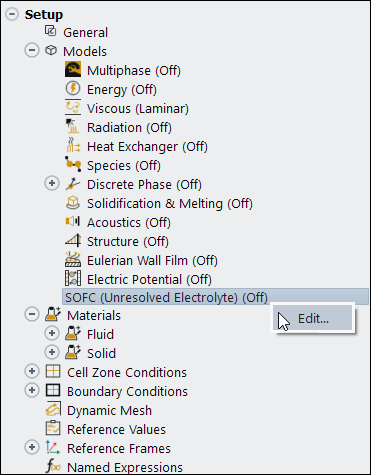
When the SOFC Model dialog box opens, select the Enable SOFC Model option.
The following describes an overview of the procedure required in order to use the SOFC With Unresolved Electrolyte Model in Ansys Fluent.
Start Ansys Fluent.
You must start Ansys Fluent in 3D double-precision mode. Note that the SOFC With Unresolved Electrolyte Model is only available in 3D.
Read the case file.
File → Read
→ Case...
Scale the mesh.
 Setup →
  General → Scale...
Enable the SOFC Model and set its parameters as described in Setting the SOFC Model.
Setup → Models → SOFC
(Unresolved
Electrolyte) Edit...
When you initially enable the SOFC model, Ansys Fluent automatically applies the following options and settings:
Pressure-Based Steady solver with the Absolute velocity formulation
Energy equation
Laminar viscous model
Species Transport model with Volumetric reactions and the following settings:
Inlet Diffusion: disabled (see Diffusion at Inlets in the Fluent Theory Guide)
Diffusion Energy Source: enabled (see Treatment of Species Transport in the Energy Equation in the Fluent Theory Guide)
Full Multicomponent Diffusion: enabled (see Mass Diffusion in Laminar Flows in the Fluent Theory Guide)
Thermal Diffusion: enabled (see Mass Diffusion in Laminar Flows in the Fluent Theory Guide)
F-cycle for AMG solver for all equations
Metis method for parallel partition with Laplace smoothing
Ansys Fluent also automatically creates the following materials (if they have not been defined in your case yet):
mixture material
The new mixture material consists of the h2o, o2, h2, and n2 species and uses the following definitions for the material properties:
ideal-gas-mixing-law for the Thermal Conductivity and the Viscosity
diffusivity::sofc user-defined function for Mass Diffusivity
E_Conductivity::sofc user-defined function for UDS Diffusivity
solid materials:
anode-collector-default
anode-default
cathode-collector-default
collector-default
You can edit these material definitions or create new solid materials for your case.
Important: Note that although the Ansys Fluent SOFC with Unresolved Electrolyte Model does support the shell conduction model that you use to take into account the transversal conductive heat inside the electrolyte material, it does not currently support a similarly transversal conduction of electric current inside the electrolyte.
You can adjust these settings as appropriate for your case. If you consider H2/CO electrochemistry, ensure that your mixture material include CO and CO2 as well.
Set the boundary conditions and operating conditions as appropriate for your case.
Setup →  Boundary Conditions
Setup →
Boundary Conditions → Operating
Conditions...
Boundary Conditions
Setup →
Boundary Conditions → Operating
Conditions...
Define the convergence criteria.
Solution →
Monitors → Residuals
Edit...
In the Residual Monitors dialog box, set the Convergence Criterion for all equations to
1e-08.Initialize the flow field.
Solution →
Initialization →
Initialize
Retain the default values for all parameters.
Descriptions of UDMs are listed in Table 32.6: User-Defined Memory Allocations.
The current density in UDM-0 is a conservative flux of
electricity (A/m2). Performing an area integral over the
electrolyte surface will sum to the total current ( ). That value is computed at the electrolyte faces during the
electric field solution. The values in
). That value is computed at the electrolyte faces during the
electric field solution. The values in UDM-4 through
UDM-6 contain cell-centered values of the current
density vector. These are not, and cannot be, conservative, so depending on the
material conductivity and the geometric configuration, these can sometimes
unavoidably produce values that do not match the UDM values. The same issues exist
when interpolating velocity values to obtain the mass fluxes.
Table 32.6: User-Defined Memory Allocations
| UDM Name | Description |
UDM-0
| Interface Current Density (A/m2) |
UDM-1
| Nernst Potential (Volts) |
UDM-2
| Activation Overpotentail (Volts) |
UDM-3
| Volumetric Ohmic Source (W/m3) |
UDM-4
| x Component of the Current Density (A/m2) |
UDM-5
| y Component of the Current Density (A/m2) |
UDM-6
| z Component of the Current Density (A/m2) |
UDM-7
| Electrolyte Voltage Jump |
UDM-8
| Electrolyte Resistivity (Ohm-m) |
UDM-9
| Effective Electric Resistance |
UDM-10
| Anode Activation |
UDM-11
| Cathode Activation |
UDM-12
| Electrochemical Source (W/m3) |
UDM-13
| Magnitude of Current Density (A/m2) |
Note that UDM-7 and UDM-8 are
the linearized values that Ansys Fluent uses to solve the potential field and
electrochemical coupling. They are necessary to the calculations but do not contain
any real physical meaning.
Note that UDM-10 and UDM-11
contain the disaggregated activation polarizations at the anode and cathode.
By default, the Ansys Fluent SOFC With Unresolved Electrolyte Model defines a single user-defined scalar:
Note:
For field variables that are stored in UDM, use the corresponding variables for post processing. Postprocessing the UDM itself is not recommended.
For reviewing simulation results in CFD-Post for cases involving UDM or UDS, export the solution data as CFD-Post-compatible file (.cdat) in Fluent and then load this file into CFD-Post.
The inputs for the SOFC model are entered in the SOFC Model dialog box using the following tabs:
Model Parameters
Electrochemistry
Electrolyte and Porous Zones
Electric Field
Customized UDFs
A detailed description of the SOFC model inputs is given in the following sections:
In the Model Parameters tab, you can specify the general settings for the SOFC With Unresolved Electrolyte Model.
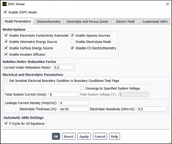
From this tab, you can set the various parameters for the SOFC With Unresolved Electrolyte Model such as total system current, electrolyte thickness, electrolyte resistivity, and so on.
In the Model Options group box, select the appropriate SOFC model options. The following options are available:
- Enable Electrolyte Conductivity Submodel
This option allows the ionic conductivity (or resistivity) of the electrolyte to change as a function of temperature. The correlation that provides ionic conductivity (or resistivity) of the electrolyte as function of temperature is expressed as:

(32–2)
Important: Note that this is valid only for temperatures ranging from 1073 K to 1373 K.
This option should be selected if the electrolyte resistivity changes as a function of temperature.
- Enable Volumetric Energy Source
This option includes the ohmic heating throughout the electrically conducting zones. You should keep this option turned off (to avoid slowing the convergence rates) until a certain rate of convergence for the potential field has been achieved, at which point, you should turn the option on manually. Note that this option is important so that the solution can account for the effects of the internal Ohmic heating.
- Enable Surface Energy Source
When enabled, Ansys Fluent excludes the heat addition due to electrochemistry and all the reversible processes. This option must be turned on at all times.
- Enable Knudsen Diffusion
When enabled, Ansys Fluent includes the effect of Knudsen diffusion in the calculation of the effective gas diffusivity. This option is useful when the Knudsen Number (the ratio of mean free path over average pore diameter,
 in Equation 20–105 in the Fluent Theory Guide) in the porous media is
much larger then 10. See Modeling Fluid Flow, Heat Transfer, and Mass Transfer in the Fluent Theory Guide for details.
in Equation 20–105 in the Fluent Theory Guide) in the porous media is
much larger then 10. See Modeling Fluid Flow, Heat Transfer, and Mass Transfer in the Fluent Theory Guide for details.- Enable Species Sources
This option must be enabled on at all times.
- Enable Electrolysis Mode
This option reverses the SOFC to produce hydrogen and oxygen from water vapor. Note the following:
If you want to specify Total System Current, you must enter a negative value; however, if you specify a positive total current, Ansys Fluent will automatically change its sign internally.
If you want to specify Total System Voltage (Converge to Specified System Voltage option), you must enter a value larger than the open-circuit voltage of the cell.
- Disable CO Electrochemistry
This option must be enabled if there is carbon monoxide (CO) in the fuel line and if you do not want to include the CO in the electrochemistry. This option is unavailable with Enable Electrolysis Mode.
Set the Current Under-Relaxation Factor to a value of either
0.3or0.2.These values are recommended for a more effective solution since the calculations are very sensitive to large current fluctuations early in the solution process.
Set the Electrical and Electrolyte Parameters according to your problem specification.
The following parameters and options are available:
Total System Current
Converge to Specified System Voltage
You can use this option when you want to specify a Total System Voltage instead of Total System Current as an input.
Set Individual Electrical Boundary Condition from Boundary Conditions Task Page
When enabled, the option allows you to directly specify the current density or voltage for each individual current-collecting boundary using the Ansys Fluent Boundary Conditions task page. This allows you to apply multiple current types or multiple voltage types (either constant or variable) to your boundary conditions.
Leakage Current Density
This is the total amount of current due to the leakage of oxidizer to the fuel side (through the electrolyte) and the electric current across the electrolyte due to any short circuit.
If the leakage current density is temperature-dependent, you can specify your own temperature-dependent implementation of the leakage current density by performing the following steps:
Make the required changes to
Leakage_Current_Density(real
                                                T)
which is a real function in the user-modifiable source code,constit.c. See User-Accessible Functions for the Solid Oxide Fuel Cell With Unresolved Electrolyte Model for details.Compile
constit.cand make your ownsofcUDF library.
By default, the F-Cycle for All Equations option is enabled in the Automatic AMG Settings group box. Once you click OK or Apply in the SOFC Model dialog box, this option sets the multigrid cycle type to F cycle for all equations that are being solved. This is a recommended setting. However, you can adjust the equation cycle settings in the Advanced Solution Controls dialog box.
In the Electrochemistry tab, you can specify electrochemistry settings for the SOFC With Unresolved Electrolyte Model.
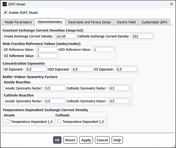
In the Electrochemistry tab, you can set the anode and cathode exchange current density, the anode and cathode mole fraction reference values, the concentration exponents, the Butler-Volmer symmetry factors, and the temperature-dependent exchange current density.
Enter values for the Constant Exchange Current Densities for the anode and the cathode. These are the
 values in the Butler-Volmer equation (Equation 20–118) for the anodic and
cathodic reactions. By default, the Anode Exchange Current
Density is set to
values in the Butler-Volmer equation (Equation 20–118) for the anodic and
cathodic reactions. By default, the Anode Exchange Current
Density is set to 1e+10Amps and the Cathode Exchange Current Density is set to100Amps.Enter values for the Mole Fraction Reference Values.
These are the species concentrations at which the exchange current densities were taken (Equation 20–119-Equation 20–121). These are used to adjust the
 values of reactant species that are depleted. By
default, H2 Reference Value, O2
Reference Value, and H2O Reference
Value are set to
values of reactant species that are depleted. By
default, H2 Reference Value, O2
Reference Value, and H2O Reference
Value are set to 1moles/moles.In the Concentration Exponents group box, enter values for the H2 Exponent, H20 Exponent, and O2 Exponent (defaulted to
0.5). These are the stoichiometric factors in the electrochemical reaction equation. They are used as exponents as part of the scaling (Equation 20–120 and Equation 20–121.
Enter values for the Butler-Volmer Symmetry Factors by setting values for the Anodic Transfer Coefficient (
 in Equation 20–118) and the Cathode Transfer Coefficient
(
in Equation 20–118) and the Cathode Transfer Coefficient
( in Equation 20–118) for both the anode reaction and the cathode reaction. By default,
these values are set to
in Equation 20–118) for both the anode reaction and the cathode reaction. By default,
these values are set to 0.5because of the nearly universal assumption that there is a symmetric balance between the forward and backward reactions. In most cases, these default values will be sufficient. These are the alpha values in the Butler-Volmer equation (Equation 20–118). They represent the forward and backward rates of reaction at both the anode and cathode.If you find yourself changing the Butler-Volmer symmetry factors, or if you have some other rate-limiting reaction in your fuel cell simulation, you may also want to consider changing the exponents for the stoichiometric coefficients for the fuel cell reactants. These exponents can be specified in the Concentration Exponents group box.
If you want to consider the temperature dependence of the exchange current density at the anode and/or cathode side, select Temperature Dependent I_0 and specify A and B (rate coefficients in Equation 20–122 in the Fluent Theory Guide) at the anode and/or cathode (Temperature Dependent Exchange Current Density group box).
In the Electrode and Porous Zones tab, you can set the anode and cathode interface components as well as the porous zones parameters for the SOFC With Unresolved Electrolyte Model.
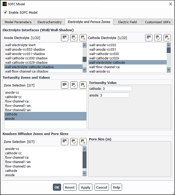
In the Anode Electrolyte multiple-selection list, select zones that represent the anode electrode interface with the electrolyte.
In the Cathode Electrolyte multiple-selection list, select zones that represent the cathode electrode interface with the electrolyte.
Set up the tortuosity parameters.
In the Tortuosity Zones and Values group box, select appropriate porous zones from the Zone Selection multiple-selection list.
As required, assign tortuosity values to any porous zones (under Tortuosity Value). In a porous zone, the mass diffusion coefficient is reduced as follows due to the porosity effect:

(32–3)
There typically are no standard means of measuring tortuosity as it must be either measured experimentally or tuned to match other experimental data. Tortuosity value may typically be in the range of
2to4, although you can use much higher values.
When the Enable Knudsen Diffusion is selected in the Model Parameters tab of the SOFC Model dialog box, set up the Knudsen diffusion parameters.
In the Knudsen Diffusion Zones and Pore Sizes group box, select appropriate porous zones from the Zone Selection multiple-selection list.
Under Pore Size , assign an effective radius of the pore (
 in Equation 20–105 in the Fluent Theory Guide) to each selected porous
zone.
in Equation 20–105 in the Fluent Theory Guide) to each selected porous
zone.
In the Electric Field tab, you can set the parameters for the electric field model.
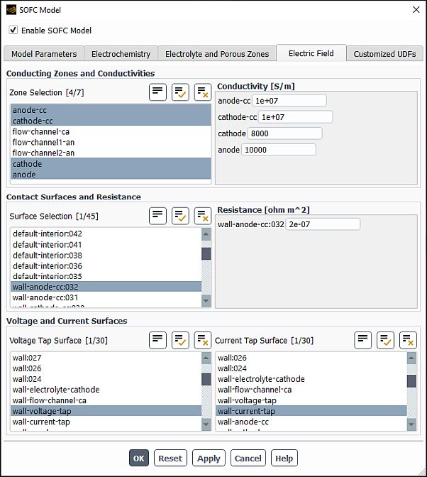
Here, you can designate conductive regions and specify their conductivity, assign boundaries to be contact surfaces and specify the contact resistances, as well as specify which surfaces are grounded and which surfaces exhibit a current.
Select electrically conductive regions from the Conducting Zones and Conductivities multiple selection list, and for each region, set its Conductivity.
Select contact surfaces from the Contact Surfaces and Resistance multiple selection list and specify their Resistance.
Select a voltage tap surface.
The Voltage Tap Surface is the surface that is grounded (that is,
 ).
).Select a current tap surface.
The Current Tap Surface is the surface that current is being drawn from (that is,
 is assigned a value).
In the Customized UDFs tab, you can select and compile your user-defined function (UDF) to customize the SOFC module.
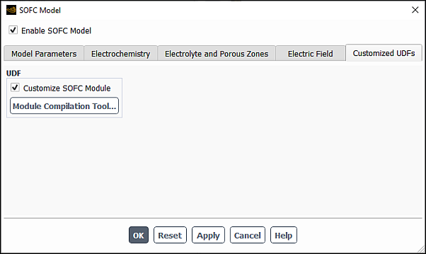
See Customizing the PEM Fuel Cell Module for details on how to compile your UDF.
You can directly incorporate your own formulations and data for the properties of
the solid oxide fuel cell model using the constit.c source
code file.
The following listing represents a description of the contents of the
constit.c source code file:
-
real Nernst(real sp_a[], real sp_c[], real P_a, real P_c, real
                            T_a, real T_c, real *DNDY)
Returns the Nernst potential using Equation 20–114.
-
real Activation(real Y[], real P, real T, real i, real i_0_ref,
                            real alpha_a, real alpha_b, int species, real *dA_di)
Returns the activation overpotential by solving Equation 20–119.
-
real Resistivity(real T) Returns the electrolyte resistance (either a constant value, or computed using Equation 32–2).
-
real Leakage_Current_Density(real T) Returns the leakage current density specified in the SOFC Model dialog box and can be overwritten as a function of temperature.
-
real Solve_Butler_Volmer_NR(real i, i_0_ref, real A, real B,
                            real *detadi);
Returns the activation overpotential by solving Equation 20–119.
-
real CONDUCTIVITY_CELL(cell_t c, Thread *t) Returns the cell conductivity value used in the Electric Field tab of the SOFC Model dialog box. This function can be overwritten to look up the conductive zone group ID (1 through 5). A conditional statement allows you to perform various tasks for respective conductive zones. For non-conductive zones, this function returns a value of 0.
-
real CONTACT_RESIST_FACE(face_t f, Thread *t) Returns the contact resistance value used in the Electric Field tab of the SOFC Model dialog box. This function can be overwritten to look up the contact resistance group ID (1 through 3). A conditional statement allows you to perform various tasks for respective contact resistance surfaces. For non-contact resistance surfaces, this function returns a value of 0.
-
real h2_co_split_func(cell_t c_an, Thread *t_an) Returns the
 /
/  split factor defined in Equation 20–138. This can be overwritten
as needed to define your own split factor.
split factor defined in Equation 20–138. This can be overwritten
as needed to define your own split factor.