


This section provides theoretical background about the reacting channel model. Information can be found in the following sections:
For more information about using the reacting channel model, see Reacting Channel Model in the User's Guide.
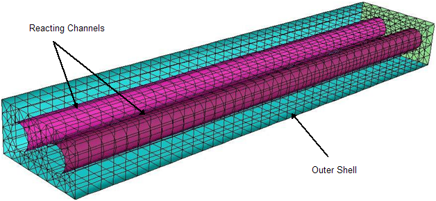
Some flow geometries contain long, thin channels (also called pipes or ducts) with reacting fluid inside the channels exchanging heat with the fluid outside the channels. Examples of such shell-and-tube configurations include fuel reformers and cracking furnaces. The flow inside the channels rapidly establishes a stationary, fully-developed radial profile. The evolution of chemical species and temperature in these channels can be accurately modeled with lower dimensional models, often assuming parabolic flow. This is much more efficient than resolving the mesh inside the channels and using a 3D solver for both flow and chemistry inside and outside the channels simultaneously. The reacting channel model inside Ansys Fluent allows affordable simulations of reactors with simple flow but complex chemistry occurring in long, thin channels, thermally coupled to geometrically complex outer flows with simple, or no, chemistry.
For the limitations that apply to the Reacting Channel model, see Overview and Limitations of the Reacting Channel Model in the Fluent User's Guide.
In the reacting channel model, all channel walls must be geometrically resolved in three-dimensions. However, only the geometry in the outer shell should be meshed; no cells should be included inside the channel walls. Figure 7.2: Cross-section of a Channel and Outer Shell Around It. shows a typical configuration with two circular channels and an outer shell around it. The flow inside the channels is reacting, while the outer flow in the shell can be reacting or non-reacting. The channel walls are non-permeable and only heat transfer can take place through them.
During an Ansys Fluent iteration, the flow inside the reacting channel is solved using fixed wall temperatures from the 3D outer flow, and then the 3D outer flow is solved using fixed heat fluxes from the channel solver.
The flow inside the channels is assumed to be a plug flow, which means that the flow variables at any axial location are radially uniform. Axial diffusion of heat and species are also ignored and therefore change only by reaction. The plug flow evolution equations for the channel species and temperatures are
 | (7–134) |
| where, | |
|
| |
|
| |
|
| |
|
| |
|
| |
|
| |
|
| |
|
|


The reaction channel convective heat transfer source  is determined as
 | (7–135) |
| where, | |
|
| |
|
| |
|
|


The channel wall temperature  (not to be mistaken with the channel bulk
temperature
(not to be mistaken with the channel bulk
temperature  ) is averaged from the 3D outer flow temperature
field on the resolved channel wall, as described below.
) is averaged from the 3D outer flow temperature
field on the resolved channel wall, as described below.
The heat transfer coefficient  in Equation 7–135 is calculated as
 | (7–136) |
where  and
and  are the gas-phase thermal conductivity and the channel
diameter, respectively. The Nusselt number,
are the gas-phase thermal conductivity and the channel
diameter, respectively. The Nusselt number,  , in
the above equation is calculated from empirical correlations for fully
developed pipe flow as follows:
, in
the above equation is calculated from empirical correlations for fully
developed pipe flow as follows:


The plug flow equations are solved with a stiff ODE solver using time-steps based on the grid size (size of channel element) and the local channel velocity.
When the surface reaction option is enabled, additional source terms due to surface reactions are added to Equation 7–134. Details of the heat and mass sources due to surface reactions are described in Wall Surface Reactions and Chemical Vapor Deposition. The reacting surface area of a reacting channel element is calculated as
 | (7–140) |
where  is the volume of the channel element and
  is the area to volume
ratio of the catalytic surface.
is the area to volume
ratio of the catalytic surface.
Note: In the reacting channel model, the heat source due to surface reaction and the heat and mass source due to mass deposition are always included.
The porous medium option in the reacting channel model uses the superficial velocity porous formulation. Ansys Fluent calculates the superficial mixture velocities based on the volumetric flow rate in a porous region.
When the Porous Medium option is enabled, the heat transfer coefficient calculated from Equation 7–136 is modified to account for the solid material of the porous medium in the following manner.
 | (7–141) |
where  is the porosity and
  is the conductivity of the solid material. Also,
the reaction rates
is the conductivity of the solid material. Also,
the reaction rates  are modified by multiplying
  by medium porosity
  to account for the displacement
of the gas by the solid.
to account for the displacement
of the gas by the solid.
The Porous Medium option provides the capability to model pressure drop inside the reacting channel. The pressure drop in the channel is calculated only in the axial direction and has contributions from viscous and inertial resistances:
 | (7–142) |
The pressure drop due to viscous resistance is calculated using Darcy's law
 | (7–143) |
where  is the viscous
resistance along axial direction and
is the viscous
resistance along axial direction and  is the length of the channel element.
The pressure drop due to inertial losses is modeled as
 | (7–144) |
where  is
the inertial resistance along axial direction and
is
the inertial resistance along axial direction and  is the length of the channel element.
The outer shell can be any arbitrarily shaped 3D geometry, but must resolve the channel walls. Note that while this outer shell is meshed in Ansys Fluent with finite-volume cells, the inside of the channels should not be meshed. This outer flow can be a reacting or non-reacting mixture, which is typically a different mixture material than the complex mechanism material used for the reacting channel plug flow.
The Ansys Fluent energy solution of the outer shell flow uses a prescribed heat flux boundary condition at the channel walls from the solution of the reacting channel. The value of this heat flux is calculated as an under-relaxation of the heat gained from the channel:
 | (7–145) |
where  is the channel heat gain/loss,
  is a user-specified
under-relaxation parameter, and
is a user-specified
under-relaxation parameter, and  is the heat flux from the previous iteration. At convergence, the
heat loss/gain from the channel is equal to the heat gain/loss in
the shell outer flow.
is the heat flux from the previous iteration. At convergence, the
heat loss/gain from the channel is equal to the heat gain/loss in
the shell outer flow.