


In this section you will view and edit boundary layers, adjust Global y+ settings and use advanced options within OptiGrid.
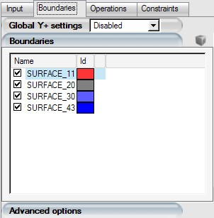
Checkmark to select each labeled surface present in the grid file. The selected boundaries are shown in the graphical window.
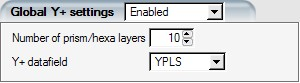
Global Y+ settings determines the constraints within which OptiGrid must operate when adapting layers of prismatic or hexahedral elements based on y+ values. Use to activate y+ adaptation.
Note: If the grid has prismatic layers: After the CAD construction step, OptiGrid will set up automatically a Constant height setting onto the detected boundaries, along with the number of layers defined in the grid.
If no y+ adaptation is activated, all elements, including any prismatic elements, will be adapted in the same way, based on the solution error. In this case, the thickness and shape of the prism layer will not remain constant from the initial grid to the adapted grid. For this reason, it is suggested that y+ surfaces be selected for turbulent flows.

Select the Number of prism/hexa layers. For hexahedra grids, only elements within the prescribed number of layers close on the selected walls will be affected by y+ corrections. The other elements will be adapted based on the error estimate.
Prisms are generally used in hybrid grids (with tetrahedral elements) to improve grid quality and orthogonality near walls. In this case, enter the total number of prisms normal to the wall, or within the prism layer.
This option is available only for Specified Height option in the Y+ prism/hexa section (See Constraints on Hexahedral/Prismatic Elements).
The y+ variable should be read from the input flow solution. Select for Y+ datafield.
Different options are offered for hexahedral and prismatic (hybrid) grids:
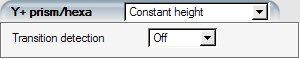
Constant height maintains the height of the layers at its original value.
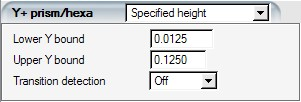
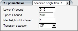
allows controlling the height of the layers directly by setting limits on the Y value (normal distance from the wall) of the nodes in the selected layers. For this, select a Lower Y bound and an Upper Y bound. These parameters indicate the Y value (not the y+ value) of the first node from the wall and of the last node in the layers. OptiGrid scales the height of the layers so that the outer nodes satisfy these bounds and the node distribution within the layers satisfies the equidistribution principle of the error.
allows controlling the height of the layers indirectly by setting limits on the Y+ value of the nodes. Select a Lower Y+ bound and an Upper Y bound. These parameters indicate the y+ value of the first node and the Y value of the last node from the wall. OptiGrid scales the height of the layers so that the outer nodes satisfy the bounds and the node distribution within the layers satisfies the equidistribution principle of the error.
The height of the first layer is reduced to the Max height of first layer if it exceeds its limit. The clipping is intended to occur in regions of very small Y+ (leading edge stagnation point, reversed flow separation point) in order to prevent large cells from being created. In such a case, the target lower y+ bound may not be respected.
Note: For centroid-based finite volume solvers, the y+ values may be averaged at the centroid of the first cell on the wall. Care must be taken to differentiate the Y+ displayed by the CFD solver’s post-processor and the y+ defined at nodes by OptiGrid.

Transition detection is used to detect zones where very small y+ occur (leading edge stagnation point, reversed flow separation point) in order to use the solution error as the criterion for adaptation in these regions instead of y+. This prevents large cells from being created in these critical flow regions. This option should be used only with layers of prisms or hexahedra when logarithmic wall functions are used by the turbulence model. In the current version, this treatment is available only when there is more than one layer of prisms or hexahedra.
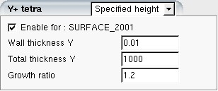
Y+ adaptation can be applied to unstructured tetrahedral meshes. or may be specified if the height is to be controlled in terms of, respectively, y or y+. For the chosen method, the lower and upper limits of the boundary layer must be entered (Wall thickness Y or y+, Total thickness Y or y+) as well as a Growth ratio inside the boundary layer. No correction can be used to switch off y+ adaptation in tetrahedral cells above layers of prisms if it is not desired to extend the y+ adaptation beyond the prisms.
The possibility to adapt the tetrahedral cells above the prisms is most useful when only one layer of prisms is used. can be used effectively with mesh smoothing to generate more cells in the boundary layer on no-slip walls.
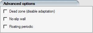
More options can be specified for each boundary by clicking the Advanced options toolbar.
Dead zone indicates that nodes on this boundary will not be adapted by OptiGrid.
Situations may occur where you wish to freeze the nodes in certain portions of the mesh. To accomplish this, you can divide the volume into several families while generating the mesh, and then define selected volume families as dead zones of adaptation.
Note: If a volume is defined as a dead zone of adaptation, you must be careful to avoid defining a column of prisms that spans both a dead zone and an active zone; in such a case, unpredictable behavior may occur.
This option ensures that a zero velocity is imposed on all selected boundaries. This feature is useful when reading solutions from finite volume codes (for example Fluent), for which the solution must be reconstructed from cell to node data. This feature ensures that a zero velocity on walls will be enforced on the specified no-slip wall families. By default, no correction to the solution is performed.
This option can be used to set the velocity to zero on walls with an Euler flow solution if a viscous solution is to be computed on the adapted grid afterwards.
This option keeps node periodicity during mesh adaptation. All nodes on one periodic surface will be adapted the same way as nodes on the opposite periodic surface.
Note: All periodic surfaces should be assigned during CAD construction, requiring manual CAD edition (See OptiGrid - CAD Reconstruction).