


The following sections of this chapter are:
OptiGrid requires CAD information to perform various geometric operations including projections onto surfaces, normal computations, etc. CAD information permits the adaptation process to be more accurate as it contains the geometry of the problem, described using parametric objects like splines, planes and lines.
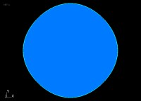
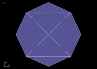
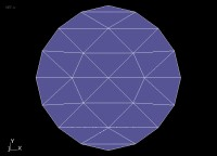
The next figure presents the CAD of a simple circle. The coarse mesh generated from this CAD shows line segments that make the original circle look like an octagonal object, which is far from the original circle geometry. By performing mesh adaptation, however, more grid points can be added on the circle boundary and its discretization in space is therefore finer, getting closer and closer to the original circle geometry. The addition of extra grid points is only possible if the CAD of the circle is known a-priori. Adding grid points based only on the original coarse mesh would have kept the octagonal shape of the geometry.
CAD reconstruction is the process by which CAD information is deduced from a raw mesh with no, or few, geometrical information. It offers many advantages among which the use of any grid, generated initially with an unknown or unsupported CAD format, with OptiGrid. Naturally, the accuracy of the reconstructed CAD is a function of the density and the location of the grid points on all surfaces of the original grid. For example, it is therefore important to use a sufficiently fine grid for capturing zones of high curvature.
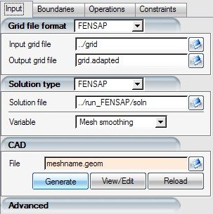
Automatic CAD reconstruction can be performed in OptiGrid using Generate. Manual CAD edition can be performed using .