The configuration parameters for DROP3D calculations have been described in DROP3D - Droplet and Ice Crystal Impingement. The following sections describe the additional features exclusive to the computation of droplet and/or ice crystal impingement in turbomachinery components.
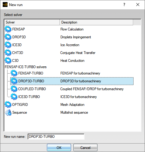
Droplet and ice crystal calculations of turbomachinery components are simulated by choosing a DROP3D-TURBO run in the New run dialog box. Each row is run sequentially in DROP3D-TURBO to utilize maximum CPU usage per row. Interactions between interfaces are done through files containing pitch averaged information.
The airflow solution sets up the inertial drag experienced by droplets and ice crystals and allows for an accurate computation of particle impact zones. Air solutions are assigned in the Air Solution section of the Model panel:
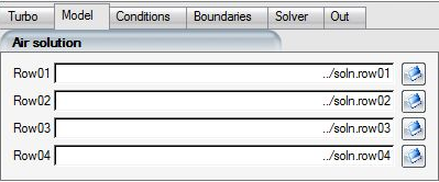
Click the  button to open the file browser and select the airflow solution
file that corresponds to each component in the list.
button to open the file browser and select the airflow solution
file that corresponds to each component in the list.
Tip: The airflow solutions of each component can also be assigned automatically in the project window by dragging & dropping the config icon of the FENSAP-TURBO run onto a DROP3D-TURBO config icon. The drag and drop operation also automatically copies the common airflow reference and input parameters for the particle impingement calculation.
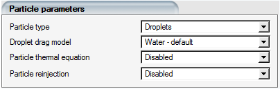
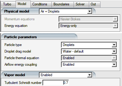
The Particle parameters section of the Model panel contains several models that impact the icing solution on a turbomachinery component:
Table 9.4: DROP3D-TURBO Physical Model
| Particle type | Droplets or Crystals or Droplets+Crystals |
| Particle thermal equation | or Disabled |
| Mass reinjection (Turbo only) | Disabled, Simple Reinjection, Complete Reinjection |
Vapor can also be within a turbomachinery component. This provides a more realistic icing environment.
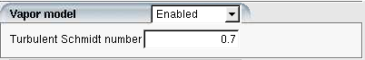
It is possible to run either droplets, crystals, vapor or all particle types in a simulation. For static components, the Eulerian two-phase model described in The Physical Model is used to solve for crystal or droplet impingement while the Vapor model is used to predict the transport of water vapor. For rotating components, the Eulerian equations are modified to include the rotational body forces:


where the subscript r refers to the velocity in the
rotational frame,  and
and  refer to the particle concentration (LWC or ICC) and the
particle velocity, respectively, and where
refer to the particle concentration (LWC or ICC) and the
particle velocity, respectively, and where  and
and  refer to the vapor concentration and the air velocity,
respectively. The force term
refer to the vapor concentration and the air velocity,
respectively. The force term  on the right-hand side of the momentum equations, representing
the centrifugal and Coriolis forces acting on the particles, is activated for
rotating frames:
on the right-hand side of the momentum equations, representing
the centrifugal and Coriolis forces acting on the particles, is activated for
rotating frames:

Supercooled droplets or crystals entering a turbomachine warm up progressively, but not at the same rate as the airflow. In this manner, the temperature difference between the particle and the surrounding airflow increases as particles travel through the compressor.
The particle thermal equation is:

The source term  accounts for the transfer of energy between the droplets
and/or ice crystals and the airflow. The term can be sub-divided to include
terms such as convection with airflow, absorption or emission due to radiant
energy, and addition or losses due to mass coupling effects that cause
evaporation, condensation, freezing or melting:
accounts for the transfer of energy between the droplets
and/or ice crystals and the airflow. The term can be sub-divided to include
terms such as convection with airflow, absorption or emission due to radiant
energy, and addition or losses due to mass coupling effects that cause
evaporation, condensation, freezing or melting:

 represents the total internal energy of the particle, such
that:
represents the total internal energy of the particle, such
that:

 is the particle concentration and
  is the specific internal energy of the particle:

 is the isobaric specific heat capacity (measured in J/(kg K))
of either the droplets or the ice crystals.
is the isobaric specific heat capacity (measured in J/(kg K))
of either the droplets or the ice crystals.
For ice crystals, the temperature is obtained directly from the specific internal energy of ice crystals:

Where  = 334,000 J/kg/k is the latent heat of fusion to melt ice
crystals.
= 334,000 J/kg/k is the latent heat of fusion to melt ice
crystals.
To activate the particle thermal equation, go to the Particle parameters section of the Model panel of DROP3D-TURBO and select the option in the Particle thermal equation pull-down menu.
The activation of the particle thermal equation adds additional fields in the solution file: particle temperature and particle specific energy, diameter and melting fraction (in the case of crystals).
The calculated melting fraction is important in determining the possibility of crystals sticking to either a dry or rime surface. The specific energy variable is used by ICE3D-TURBO in glaze ice simulations to identify the local particle enthalpy at the point of contact on the surface.
It is normal for the melting fraction to contain high values in the ice crystal shadow zones, where this quantity loses its meaning. For a more sensible view, melting fraction and ice crystal concentration are combined in Viewmerical to display the liquid phase and the solid phase of the particles.
Note: To allow mass and energy transfer between droplets/crystals and vapor, select beside the Particle thermal equation.
The Reference conditions section in the Conditions Panel sets the initial conditions for a particle impingement calculation. If the config icon of the FENSAP-TURBO run has been dragged & dropped onto the DROP3D-TURBO config icon, the airflow conditions have already been copied into the Reference conditions section automatically. Only the Droplets reference conditions need to be set.
The reference conditions for the DROP3D-TURBO run are explained in Particle Conditions.
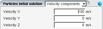
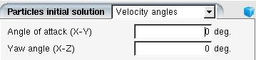
Several options are available to initialize the solution domain on all components.
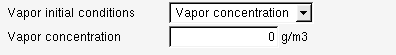
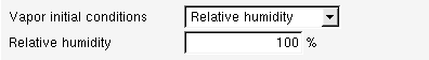
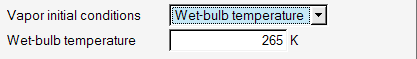
Vapor field can be initialized with vapor concentration, relative humidity or wet bulb temperature. Relative humidity ranges from 0 to 100%. It is defined as the ratio of the partial vapor pressure to the saturation vapor pressure.
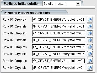
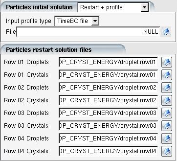
The particles solution can be restarted from a previous set of solutions by
choosing the option Solution restart in the
Particle initial solution menu. Click the browse
buttons  to open the file browser and select the particle solution
file that corresponds to each component.
to open the file browser and select the particle solution
file that corresponds to each component.
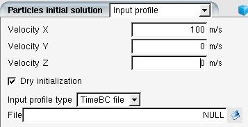
A user defined timebc file can be generated to define LWC/ICC, velocities and temperature for droplets and ice crystals entering the inlet of the first row. When the Input profile option is specified, the values in the user defined data file take priority over those specified in the Boundaries of FENSAP-ICE.
This option is useful when previous solutions are available and a similar set of solutions are desired with a new inlet condition. The inlet condition of the first row is provided by a user defined timebc file. When the Restart + profile option is specified, the values in the user defined data file take priority over those specified in the Boundaries panel of FENSAP-ICE.
Converged solutions from a different run are used to define the initial conditions for each component.
The Dry initialization option applies zero LWC/ICC/Vapor concentration to the entire domain except the inlet boundaries and can be set by putting a checkmark in the box next it. Dry initialization should always be enabled when simulating turbomachinery components to improve the rate of convergence of DROP3D-TURBO solutions.

This run type couples the equations of vapor, air, and particle energy in a thermal way. This is important when simulating realistic icing environments in engine passages. When the air energy equation is coupled with particles, droplet evaporation and crystal melting will absorb heat from the air system with a sink term included in the air energy equation. Consequently, the air temperature will decrease. This in turn will change the local humidity and the adiabatic wall temperatures, and influence the ice accretion rates on walls.
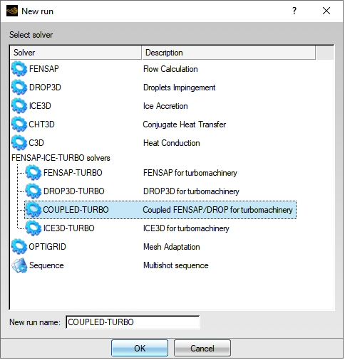
For turbo applications, the setup is similar to the standalone DROP3D run. However, a few steps need attention. First, create a COUPLED-TURBO run under FENSAP-ICE-TURBO solvers, then provide the number of rows.
If the dry air is solved by FENSAP, drag & drop the FENSAP-TURBO run onto the new COUPLED-TURBO run to inherit the grid and dry air solution. The COUPLED-TURBO run has a few presets that have already been set up. In the turbo environment, option is enforced in the two-way thermal coupling. The energy equation of the airflow is solved instead of the full Navier-Stokes equation. The Particle thermal equation and the Airflow energy coupling should be both . Vapor model is highly recommended for two-way thermal coupling, but not required.
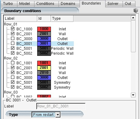
Similar to the standalone DROP3D run, the inlets and outlets of the airflow should be set as . Boundary conditions will automatically initiate from the restart solutions. Set up the particle boundary conditions as normal. Since only energy equation is solved, a larger CFL number can be used for air.
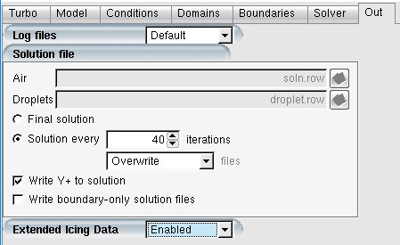
In the Out panel, Extended Icing Data should have been . Verify and ensure it is enabled since the EID information is required by the icing computation.