The configuration parameters for ICE3D calculations have been described in ICE3D - Ice Accretion and Water Runback.
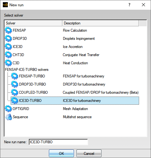
Icing calculations through set of turbomachinery components are simulated by choosing an ICE3D-TURBO run in the New run dialog box. Each row is run sequentially to utilize maximum CPU usage per row.
The prerequisites to running icing calculations are:
An airflow solution with adiabatic walls.
Droplet and/or ice crystal solutions.
A drag and drop of the configuration settings from a DROP3D-TURBO run to an ICE3D-TURBO run sets up initial parameters (such as linking solution files, copying reference conditions, assigning icing temperature).
The following sections outline the additional features exclusive to ICE3D-TURBO for the computation of ice accretion in turbomachinery components.
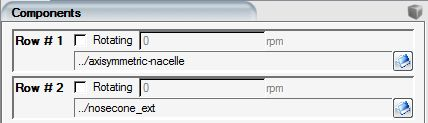
Centrifugal and Coriolis source terms are included in the governing equations for ice accretion in rotating components. The body forces are automatically activated by ensuring that component rotation is enabled and that the rotation speed is set to a non-zero value in the Turbo panel.
Drag & drop the config icon of the DROP3D-TURBO run onto the config icon of ICE3D-TURBO to import the reference settings automatically.
If other flow solvers are used, then you need to review the input settings to ensure that rotating components are set up correctly.
The drag and drop of a Crystal and Droplet run from DROP3D-TURBO will set up ICE3D-TURBO to run a simulation containing droplets and ice crystals. More options are available in the Ice crystals menu of the Model panel.

To evaluate the impact of ice crystals on an icing calculation, you can choose to run a simulation with exclusively droplets (Disabled), or exclusively with crystals (Crystals only) where the impact of droplets will not be considered.
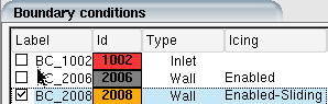
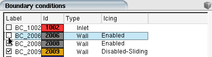
The wall boundary labels in the Boundaries panel are color coded to identify the boundary condition that has been applied.
All walls are for icing by default. An enabled wall boundary label appears grey in the Boundary panel list and in the display window.

If the wall is Disabled, the color changes to dark grey. Disabled walls are omitted from the icing calculation.

Some walls in rotating components, such as the shroud, remain stationary in the absolute frame of reference. Since rotating components are solved in the relative frame of reference, for each stationary surface activate the Counter-rotating option in the Rotation section of the Boundaries panel:

Counter-rotating walls are displayed in the boundaries list in yellow.

Counter-rotating walls experience a time-varying history, since the rotating components cause periodic variations in the flow field and particle impingement as they move. The instantaneous variation of these variables is circumferentially averaged to account for their time variation. Properties received from FENSAP-TURBO and DROP3D-TURBO are pitch-averaged on the static counter-rotating walls before starting an icing calculation.
Figure 9.7: Convective Heat Flux on the Turbofan Splitter Section Belonging to the Rotor Stage Showing the Wake of the Rotor
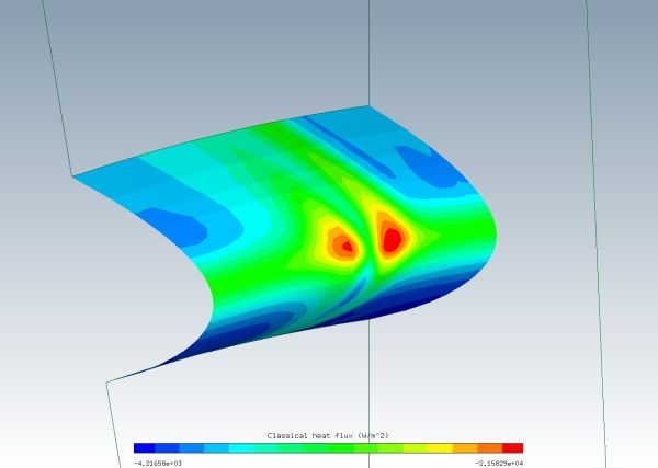
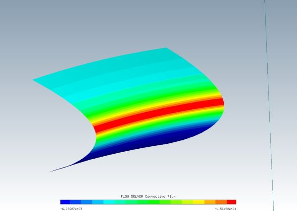
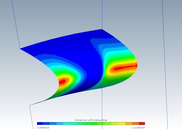
Figure 9.9: Collection Efficiency on the Turbofan Splitter Section Belonging to the Rotor Stage Showing the Wake of the Rotor
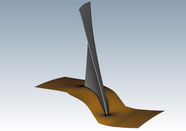
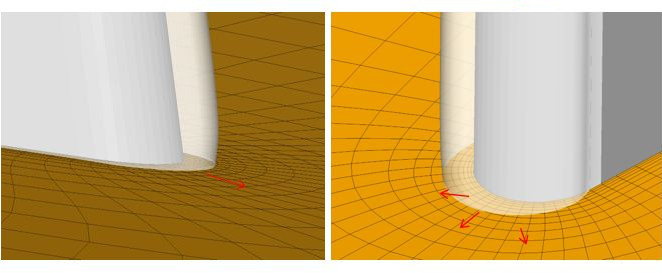
Strong differences in the ice growth rate between neighboring surfaces may cause some wall boundaries to become highly distorted, displace into each other, or move past the physical boundaries of an adjoining surface.
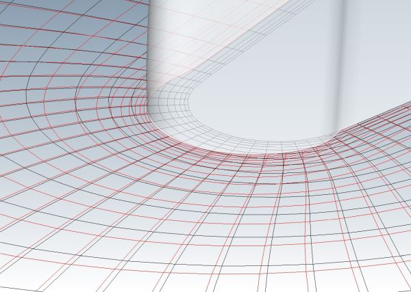
Walls where ice accretion is much less dominant than their neighbors can be defined as sliding boundaries, where ice growth is neglected to permit the adjoining surface grid to move only in a tangential direction. For more information refer to Boundary Conditions.
There are two sliding wall boundary condition options available to the user:
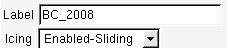
Enabled Sliding
This option allows the wall boundary to take part in the film flow and ice mass calculations, but it will be omitted when carrying out grid displacement. The wall boundary will act as a sliding surface for adjoining surfaces to slide on. The option is identified in the boundary list and appears in the display window as a light orange color.
The option is useful in turbomachinery applications when defining a hub and shroud boundary. This will allow the transfer of film between rotor-stator domains whilst allowing ice growth on the blade to slide on hub and shroud interfaces.
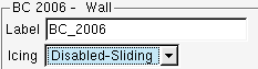
Disabled-Sliding
This option removes the wall boundary from both film flow and ice displacement calculations. The boundary will only be used to allow adjoining surfaces to slide along its contour. The option is identified in the boundary list and appears in the display window as a dark orange color.
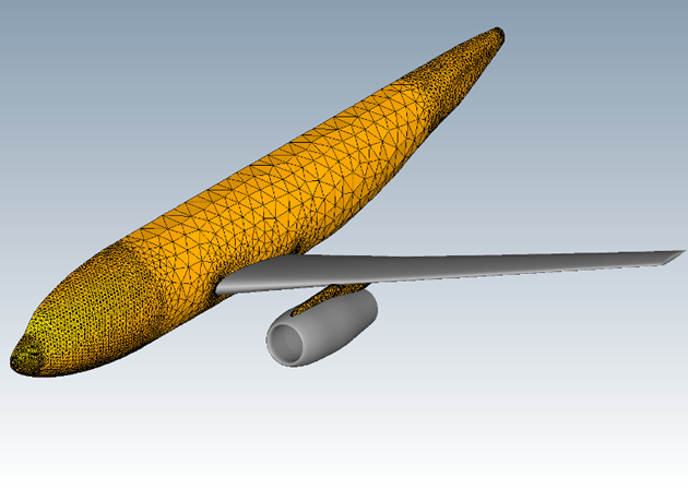
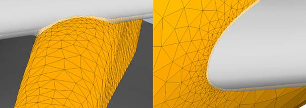
The following example shows how a boundary could be used. The geometry is a fuselage-wing-pylon configuration. In this example, the icing on the wing is of interest. The fuselage and pylon are defined as sliding boundaries.
A pooling node is identified as a node where the film becomes stationary and accumulates indefinitely. Pooling nodes are detected automatically by ICE3D-TURBO and the film on these nodes is clipped to a maximum value determined by local aerodynamic conditions.
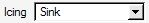
Sink nodes in ICE3D-TURBO include all nodes on a boundary that are identified by the option plus any node that touches the exit boundary. In a sink boundary, all nodes remain free of any film and ice growth.