This section is only activated if more than one domain is present in the grid file (See FENSAP-ICE File Formats for the FENSAP grid file format). A domain is composed of two or more volume elements flagged with the same material ID number.
Note: A zero (0) domain index should be assigned to all fixed domains.
Domain indices can be used to simulate rotor-fuselage interactions by separating the grid into regions that are either fixed in space, such as the fuselage, or rotating with the rotors. The calculation is always performed in the absolute frame of reference system (fixed grid), in which the rotor blades are rotating in time.
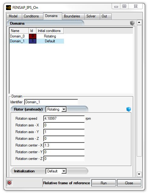
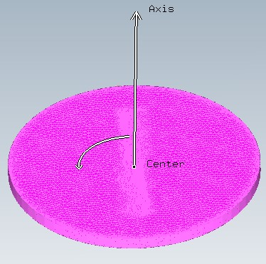
In the Rotor (unsteady) section, each domain can be configured either as Rotating or Fixed. The Rotating option should be applied only to domains with the suitable topology with a gap and interfaces boundary conditions (see Important). This will only affect the state of the initial solution vectors. When the domain is selected, the bounding box of the domain is shown in the 3D panel. For Rotating domains, the Rotation speed (in rpm), Rotation axis and Rotation center must be defined.
The transfer of flow information between rotating and fixed domains could generally be performed using either sliding boundaries or Chimera grids, but these approaches are not fully conservative. In FENSAP-ICE, a different approach has been adopted in which the fixed and rotating domains are separated in space by a small gap (similar to two concentric cylinders, one inside the other). At each time step the rotor grid is rotated by the appropriate angular displacement and the gap is remeshed, or stitched with tetrahedral elements. No new nodes are created during the stitching process, therefore this method ensures flow conservation without any special treatment.
Important: For the stitching algorithm to work properly, the inner and outer surface of each gap must be identified in the grid file with a boundary condition index ranging from 7,000 to 7,999. All gap surfaces must have unique boundary condition indices.
To ensure optimal performance of the stitching algorithm, the gap between the two surfaces should be of the same size as the element faces on the two surfaces and the mesh transition between the two domains should be as smooth as possible.
Rotor/fuselage interactions can only be computed with the unsteady flow solver, as shown later in the Solver section. Since many segregated equations are involved, time accuracy is ensured by the Newton sub-iterations at each time step.
Click the display icon ![]() to check the input data and display the material
properties:
to check the input data and display the material
properties:
Click again to remove the graphical display.
In the Solver section, select Gradually accelerate to full speed to progressively accelerate the rotor to full speed over the first few time steps.
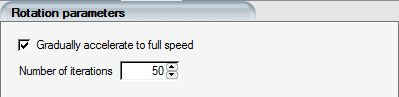
This is useful when starting the calculation from an initial uniform solution to ensure good stability and convergence of the Newton sub-iteration procedure.
Some internal flow calculations may require different initial conditions than the reference parameters to provide a better starting point for the solution algorithm. For example, the piccolo tube chambers will benefit from starting with a higher static pressure than the value set at the exit. Inside of the piccolo tubes themselves it is preferable to set total pressure and temperatures initial conditions that match their inlet boundary conditions to help jump-start the supersonic jets. Cavities inside rotating components, such as engine nose cones, experience a swirling flow driven by wall shear. To accelerate convergence, the airflow in these domains can be initialized with a rotational velocity.
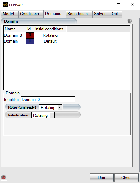
To enable multi-domain initialization, the grid file must contain more than one domain ID for the Domains panel to become visible. See The Domains Table for the format of the domain IDs in the grid file.
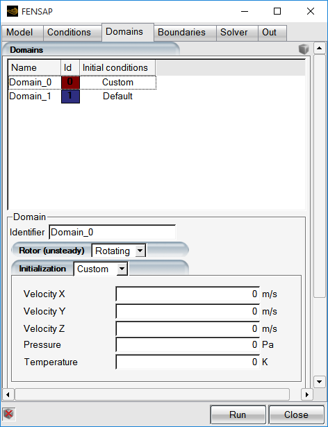
In the in the Domain Parameters in the Domains panel, Initialization can be set to Default, Rotating or Custom. The Default option uses the reference static temperature, pressure and the velocity components set in the initial conditions section of the conditions panel.
The Rotating domain initialization sets the axial velocity to zero and the angular velocity to that of the rotational frame of reference. In other words, in the rotating frame of reference the relative velocities are initialized as zero (rotating with the domain).
The Custom option permits the specification of an alternate set of flow conditions for that domain: