VMFRT007
VMFRT007
Small-Bore Direct Injection Diesel Engine
Overview
| Reference | Retrieved from Engine Combustion Network website: https://ecn.sandia.gov/Small-BoreDieselData/CFD/Engine_Geometry/SmallBore_Full_Engine_SL_Piston.stl |
| Solver | Ansys Forte |
| Physics/Models | Engine Combustion Network (ECN) - Light duty engine combustion |
| Input Files | SmallBore.ftsim |
| Project Files | Link to Project Files Download Page |
Test Case
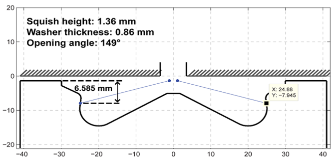
This test simulates the closed cycle combustion in a small-bore direct injection diesel engine. The engine has a 7-hole injector and here it is modeled as a (360/7)⁰ sector with a stepped-lip piston bowl and no valve cutouts as shown in Figure 209: Geometry sector and dimensions.
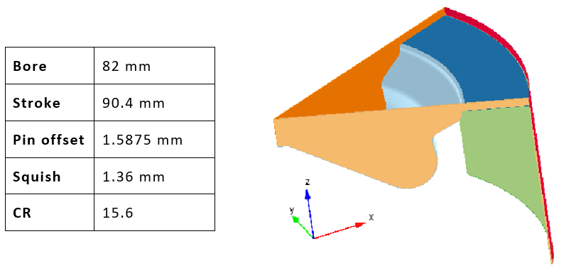
The case is labeled on the ECN website as conventional diesel combustion at part load (9bar IMEPg), CDC9_SL_SSEp17b. It operates with a pilot-main injection strategy applied with a single profile and the spray targeting data, shown in Figure 210: Spray targeting data, can be found on the ECN site at this link:
The file contains both the re-entrant and the stepped-lip piston bowl data.
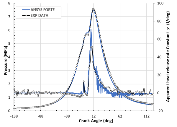
The table below lists the setup parameters, and results are compared against the experimental data. Data for the pressure trace can be found in the form of a Microsoft Excel file on the ECN site at the following link:
The file is named CDC9 InjRate Pcyl PIntake Fired and the worksheet it references is named CDC9_SL_SSEp17b. Notice that the engine has a piston pin offset of 1.5875 mm and the minimum volume occurs at -0.43 ATDC. Forte’s convention is to define piston TDC as crank angle= 0⁰, therefore the experimental curve is shifted by +0.43 degrees forward for a consistent comparison (see Slider Crank Motion in the Ansys Forte User's Guide). In addition, it is presented as the apparent heat release rate with constant gamma (𝛄=1.35) derived from the pressure trace (see Spatially averaged variables that are always output to the .csv files in the Ansys Forte User's Guide) according to:

| Test case properties | ||||||||
|---|---|---|---|---|---|---|---|---|
| Pinitial | Tinitial | Tot Minj | SOI | Durationinj | Compositionfuel | CR | RPM | Dnozzle |
|
1.74 bar |
440 K |
24.24 mg | -13.4 deg |
23.5 deg |
hmn =58,7% nc16h34 =41,3% | 15.6 | 1500 |
0.139 mm |
| Simulation Settings | ||||||||
| Tdroplet | Cd | Spray angle | SAM on ∇Vel | IVC | Mesh sizeMAX | dtinitial | ||
| 400 K | 0.8 | 12 deg | ∇T = 1 mm ∇Vel, ∇Y[a] | -138 deg | 2 mm | 5e-7 sec | ||
[a] Y=Fuel Vapor Mass Fraction