The behavior described here is expected when the Contact Detection is set to Trajectory, the Sliding Contact is set to Connected Surface, and the Manual Contact Treatment is set to Pairwise.
The scoping supported with these contact settings are:
The Target scoping must be either of type Face or Element Face, or type Body.
The Contact scoping may be of types Vertex, Edge, Face, Element Face, or Body.
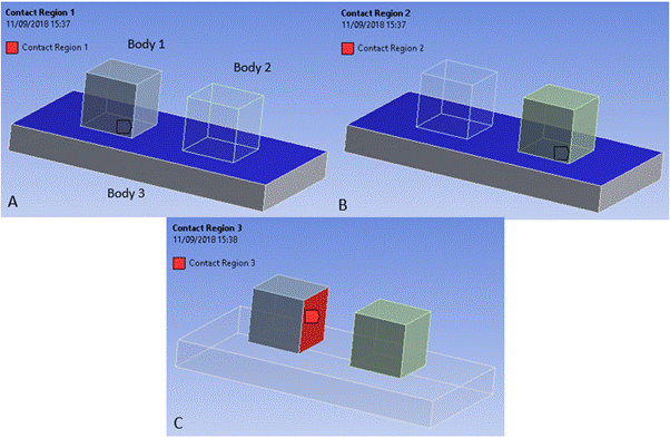
The detected contact events respect the pairwise nature of the manual contact regions. Therefore if a node is in the scoping of the Contact of one manual contact region, and a face is in the scoping of the Target of a different manual contact region, but not in the first manual contact region, then the node will not find contact with the face. See Figure 3.3: Interaction of Pairwise Manual Contact Regions for further explanation.
Manual contact regions are defined A) between the lower face of Body 1 and the upper face of Body 3; B) between the lower face of Body 2 and the upper face of Body 3;
C) between the rightmost face of Body 1 and the leftmost face
of Body 2. In this scenario the Explicit solver will not search for contact events between the
upper face of Body 3 and the rightmost face of Body 1 and the leftmost face of Body 2. Note that
this is in contrast to the treatment described in Figure 3.1: Interaction of Lumped Manual Contact Regions.
The Symmetry Behavior option is respected, but the Trim Contact option of all contact regions is ignored.
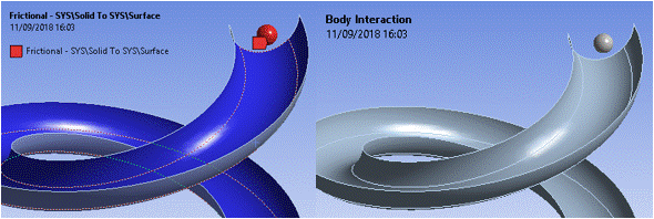
Friction coefficients are stored per contact region and per Body Interaction object in the solver. Therefore, the model described in Figure 3.4: Treatment of Friction for Pairwise Manual Contact will behave from a friction perspective as defined in the model setup. A solver setup error message is issued if conflicting friction coefficients are defined between any pair of nodes and faces in all of the scopings to manual contact regions and Body Interaction objects in the model.
In this example a frictional manual contact region is defined
between the ball and slide. In addition, a Body Interaction is
created which is scoped to all bodies and is frictionless. In this scenario the Explicit solver
will issue a solver setup error because two different types of friction behavior have been
defined between the surface of the ball and the surface of the slide.
Frictional forces are computed as described in Frictional Type.
Note: The Pairwise option for Manual Contact Treatment is not fully supported in the Autodyn user interface. If a model with the above settings is transferred to Autodyn, limited pre-processing will be available.


