The behavior described below is expected for contact detection in the following scenarios:
Contact Detection set to Proximity Based
Contact Detection set to Trajectory and either:
Sliding Contact set to Discrete Surface
Sliding Contact set to Connected Surface and Manual Contact Treatment set to Lumped
The scoping supported with these contact settings are:
The Contact scoping and the Target scoping are both of type Face or Element Face.
The Contact scoping and the Target scoping are both of type Body.
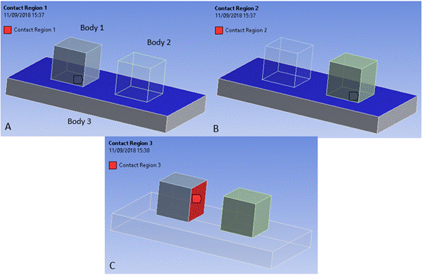
All faces and nodes in the scoping of any manual contact region or any Body Interaction object are all able to find contact with one another. Therefore, a node in the scoping of one contact region may find contact with a face in the scoping of a different contact region. See Figure 3.1: Interaction of Lumped Manual Contact Regions for further explanation.
Manual contact regions are defined A) between the lower face of Body 1 and the upper face of Body 3; B) between the lower face of Body 2 and the upper face of Body 3;
C) between the rightmost face of Body 1 and the leftmost face
of Body 2. In this scenario the Explicit Dynamics solver will also search for contact events
between the upper face of Body 3 and the rightmost face of Body 1 and the leftmost face of Body
2 even though those interactions have not been explicitly defined with manual contact
regions.
The Symmetry Behavior option and Trim Contact option of all manual contact regions are ignored.
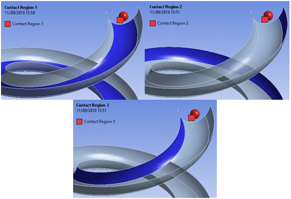
Friction coefficients are stored per pairs of bodies in the solver, and not per pair of contact scopings. Therefore, if a manual contact region has Contact scoped to faces on Body A, and the Target is scoped to faces on Body B, the friction coefficient defined for this manual contact region will be use for any contact between Body A and Body B. Care should be taken when defining friction coefficients, and a warning message will be issued if any manual contact region overwrites the friction coefficients set by another manual contact region or by a Body Interaction object. See Figure 3.2: Treatment of Friction for Lumped Manual Contact for further explanation.
In this example consisting of two parts (the ball and the
slide), three contact regions are defined. Contact Region 1 is frictionless, but Contact Region
2 and Contact Region 3 are frictional. As friction is only stored in Explicit Dynamics per pair
of parts and not per contact region, all the contact events detected during the solve will be
treated as frictional. This includes the contact events detected between the scoping in Contact
Region 1 which was defined as frictionless.
Frictional forces are computed as described in Frictional Type.


