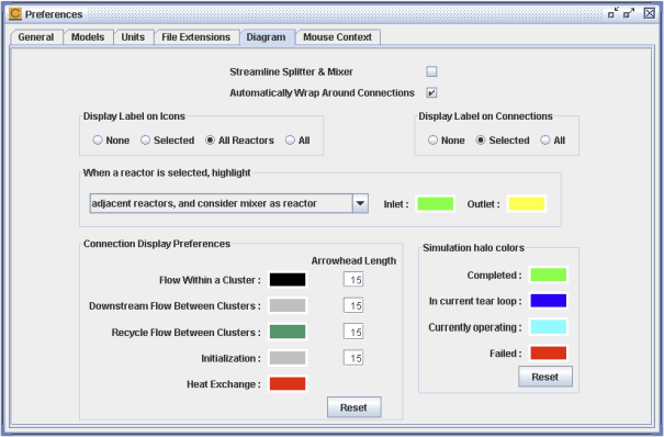
Figure 2.59: Preferences > Diagram shows the Diagram tab in the Preferences panel. This tab allows users to customize much of the drawing and display behavior in the Diagram View. It controls the colors for connection lines and reactor highlights, and the size of arrowhead on connection lines. Users can set preferences for labels on reactor icons and connections, and wraparounds of connections. There is also a choice to "streamline" splitters and mixers, which causes them to appear as a small dot adhered to the upstream reactor.
You can select whether flow-connected reactors are highlighted when a reactor is selected, which can be helpful when dealing with a complicated reactor network. The default is to display reactors providing flow into the selected reactors with a green halo and the reactors receiving flow from the selected reactor with a yellow halo (see Figure 2.27: Selected reactor in diagram with highlighted flow).
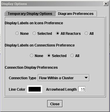
Figure 2.60: Display Options - Diagram Preferences Tab shows the Diagram Preferences tab of the Display Options panel after clicking the Display Options button on the Diagram window. This tab allows you to specify preferences for both the current diagram and any new diagram displays. (Other existing diagrams will not reflect these preferences unless they are either Updated or closed/reopened.) In addition to the label display preferences described in Rename Reactors and Inlets, you can also control the color and arrowhead length for 4 different connection types used within the diagram: Initialization, Flow Within a Cluster (inlet connections, recycle streams, flow to reactor product icon), Flow Between Clusters, and Heat Exchange. By default, the connection display settings for Flow Within a Cluster are shown. Use the Connection Type drop-list to select another connection type to see the line color and arrowhead length values for that connection type.


