


The initial step to creating a project is building a reactor diagram using the Model Palette. To demonstrate the reactor-cluster concept, including intra-cluster heat transfer, we will set up a problem that could describe a water-heating system. The water-heater will use hot exhaust gas from a natural gas burner, modeled as pure methane burning in air. The heat is transferred to the water via a heat-exchanger downstream of the burner (for example, a finned-tube compact heat exchanger). To enhance the energy efficiency of the system, a recuperator is included to recycle energy from the flue gas to pre-heat the primary air entering the burner. In Adding Selective Catalytic Reduction to the Thermal Cycle Diagram, we will expand the model further to add selective catalytic reduction of pollutant emissions to the water-heater system. In this section, we define the "thermal cycle" system with a series of PSRs representing the burner, water-heater, and heat-exchanger components.
To create a diagram for the Thermal Cycle project, complete the following steps:
Click the PSR icon. A PSR icon and an Inlet Source icon will appear on the Diagram View as shown in Figure 2.22: Thermal_Cycle Diagram—Insert First PSR. The PSR icon is highlighted in cyan. The connecting line represents the mass stream from the inlet source and the arrow shows the flow direction.
With the PSR still highlighted in cyan, add three more PSRs in series, by clicking three times on the PSR icon in the Model Palette. This should result in the Diagram View shown in Figure 2.23: Thermal_Cycle Diagram—Insert Three More PSRs. The last PSR created is highlighted with the cyan frame.
Click on the Outlet Flow to add it to the last reactor, thus indicating the end of the flow stream.
Note: You can build diagrams using drag-and-drop or select-and-click. The select-and-click action creates default connectivity, while drag-and-drop of reactor models requires manually drawn connections. When manually drawing connections, you should investigate the Context-sensitive Mousing Preference (see section Managing Preferences).
Note: Moving a group of multi-selected reactors can be done with a click and drag of the mouse while holding down the Ctrl key.
Add inlets to the second and third PSRs in the series, using two different methods. First, on the Diagram View, select the second reactor, so that it is highlighted. Then click on the Inlet Source in the Model Palette. A new inlet should appear automatically connected to the highlighted reactor on the diagram. To demonstrate an alternative connection method, drag-and-drop an Inlet Source from the Model Palette to the Diagram View area. To connect this Inlet Source to the third reactor in series, click the right side of the inlet and draw a connection to the third reactor. With context-sensitive diagramming, a connection that starts from the right side of the reactor is a gas flow connection. The result of adding these two inlets is shown in Figure 2.24: Thermal_Cycle Diagram—Inlet Streams Added to Downstream Reactors.
Note: Reactor-network components and connections can be deleted at any time in the Diagram View by selecting the item, clicking the right-mouse button, and choosing Delete Item in the short pull-down menu that appears.
Note: Multiple reactors can be deleted by drawing a selection lasso around the desired reactors with the mouse and then pressing the Delete key on your keyboard.
You can rearrange the diagram to organize your model better, by adding "joints" to the connections (click on the lines with the left mouse button and drag the joint) and by drag-and-drop of the reactor components. Figure 2.25: Thermal_Cycle Diagram—Rearranged Reactor Network shows an example of a re-organized diagram that is functionally equivalent to Figure 2.24: Thermal_Cycle Diagram—Inlet Streams Added to Downstream Reactors. Changing the Layout of Icons and Connections in Diagram View discusses methods of rearranging reactor icons.
Note: Click the Zoom button if you want to make the components of the Diagram View easier to see and manipulate. The cursor indicator becomes a horizontal arrow with a plus on the right side and a minus on the left. Click and drag to the right to zoom in and click and drag to the left to zoom out. Click the Zoom button again to return to diagramming mode.
Update the project by clicking on the Update Project button before proceeding to the next step. This will validate your project and create a project tree on the Open Projects tab.
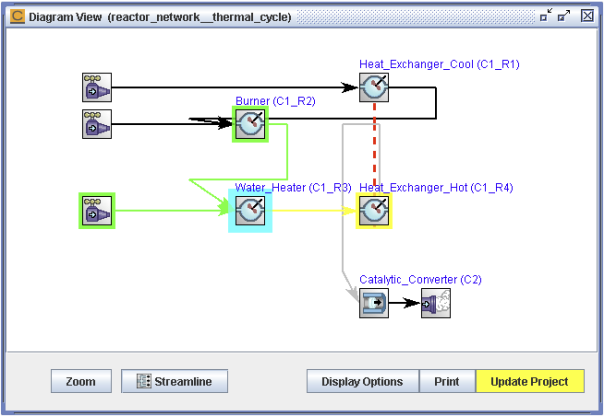
Now add a heat-flow connection between the first C1_R1 PSR and the last C1_R4 PSR. To see reactor labels, click Display Options. Select All under Display Label on Icons for Preference. Then, in the Diagram View, select the first PSR, so that it has a cyan highlight, and then, using the context-sensitive mouse cursor, click the bottom edge of the C1_R1 PSR and then draw a line to the top edge of the C1_R4 PSR. A new heat-transfer line is created, which is designated by a red dashed line.
Note: The context-sensitive diagram mode can be toggled on and off and its sensitivity or edge definitions for the reactor connections redefined on the Mouse Context tab in the Preferences panel. (Use the Preferences command under Edit.) See Managing Preferences for more details on setting the Preferences.
Note: The initial mass-flow connections of a PSR cluster must be validated using the Update button, before heat-transfer connections can be added to the diagram.
Click on Update Project again. The heat-transfer connection is now displayed with a red dashed line, indicating a valid connection, as shown in Figure 2.26: Thermal_Cycle Diagram—Validated Mass and Heat-transfer Connections. The project must be updated any time a change is made to the model diagram.
Before proceeding, save your project, using the Project > Save option. Choose a location and save the new project file. The default name will be thermal_cycle.ckprj.
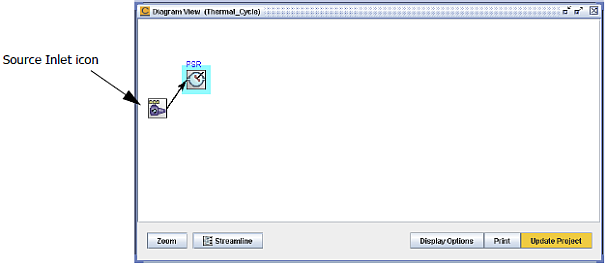
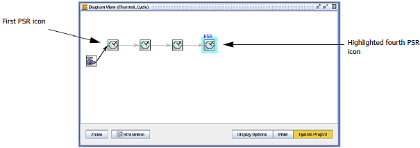
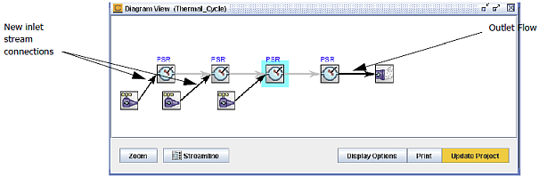
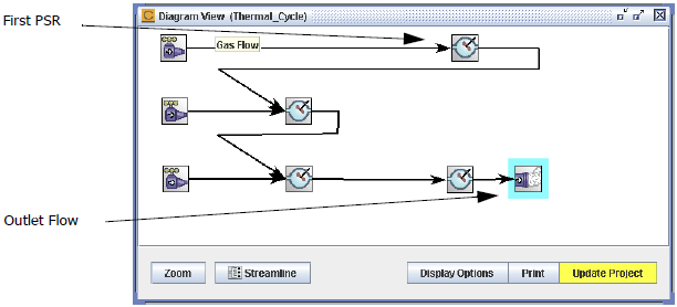

Figure 2.27: Selected reactor in diagram with highlighted flow shows the diagram with the Water Heater reactor selected and the option to also highlight reactors providing and receiving flow to/from that reactor. This option is enabled by default and can be configured using the Diagram Preferences tab (see Diagram).
Various functions are available for manipulating icons in the Diagram View.
You can re-position individual icons in the Diagram View by one of two methods:
Click in the middle of the icon and drag it to the desired location, if context-sensitive mousing is selected in your Preferences (see Managing Preferences).
If context-sensitive mousing is not selected in your Preferences:
Select the Move Icon radio button at the bottom of the Diagram View panel and then use your mouse to drag and drop icons within the diagram.
With any of the other radio buttons selected besides the Move Icon option, you can hold down the Shift key and then drag any icon you wish to reposition to a new location.
Selecting multiple icons and connections
Icons can now be multiply selected and then moved or deleted. The selection of multiple icons can be achieved in one of two ways:
Select the Move Icon radio button and then hold down the Ctrl key while clicking on all the reactors that you wish to move. The cyan highlight will appear around all the selected reactors.
Using your mouse, draw a box around all icons that you wish to move. The cyan highlight will appear around all the selected reactors.
To move icons that have been multiply selected using one of the two methods described above, simply hold down the Ctrl key and click on one of the selected reactors to drag all the selected reactors to a new location.
To delete icons that have been multiply selected using one of the two methods described earlier:
Hold down the Ctrl key and then right-click on one of the selected reactors to get the context menu; choose Delete Selected.
Select the reactors and then click the Delete key.
To create connection lines, methods differ depending on the Context-Sensitive Mouse Preference (see Managing Preferences). With the default turned on, click the specific edge of the icon to establish a particular type of connection and draw the connection line to the other reactor.
If context-sensitive mousing is not selected in your Preferences:
Select the Move Icon radio button at the bottom of the Diagram View panel and then use your mouse to drag and drop icons within the diagram.
With any of the other radio buttons selected besides the Move Icon option, you can hold down the Shift key and then drag any icon you wish to reposition to a new location.
Straightening multiple connection lines
To straighten multiple connection lines, use the first option described under Selecting multiple icons and connectionsSelecting multiple icons and connections to select all the connection lines you wish to straighten. Then right-click on any of the selected connections to get the context menu and choose Straighten Lines.