In this section we describe ways in which you might customize your Ansys Chemkin work environment and project display.
Once you have run the pre-processor, you can rename the reactors and inlets so that they have more descriptive labels that remind you of their function. By default, the reactors are labeled according to their cluster number, the reactor order in the cluster, and the Reactor Model type. Inlets are labeled according to the reactor number that they flow into and the order in which the inlet was added to the reactor. Inlet Sources, on the other hand, are labeled according to the Inlet streams that flow into a particular reactor. The reactor and inlet stream names are always displayed in the Project Tree, but are hidden by default in the Diagram View. The following steps demonstrate how to display and modify the reactor and inlet labels:
Note: The Inlet Source indicated by the ![]() icon is considered the "source of", but does not
correspond directly to the Inlet stream, the properties of which are indicated on the
Project tree panel. In this way, the Source and the Stream may have different
names.
icon is considered the "source of", but does not
correspond directly to the Inlet stream, the properties of which are indicated on the
Project tree panel. In this way, the Source and the Stream may have different
names.
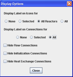
To Display the reactor and inlet names in the Diagram View, open the Diagram View panel and click the button. This opens a dialog with radio-button options for which labels to display. Select the All Reactors and All connections options, as shown in Figure 2.33: Display Options - Reactor and Connection Labels Selected, then click Close. Labels should now be displayed in the Diagram View.
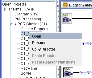
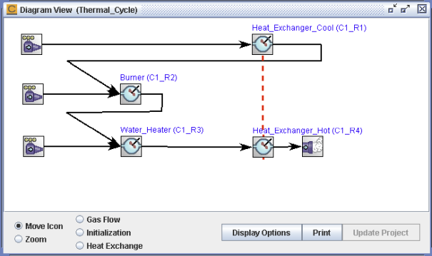
To rename the first reactor, right-click the C1_R1 PSR node in the project tree and select the Rename context menu option (see Figure 2.34: C1_R1 PSR Right-click Menu—Rename Menu Option). You can also right-click on a reactor in the diagram itself and select Rename from the context menu that appears. When prompted, enter Heat_Exchanger_Cool for the new reactor name, and click . Both the Diagram View and the Project Tree will be updated. Note that the user label always has an appended (C#_R#) so that we can remember the order of the reactor numbering for future reference. Figure 2.35: Thermal_Cycle Diagram—All Reactors Renamed shows the thermal cycle diagram with all the reactors renamed. These labels will be referred to in the next sections.
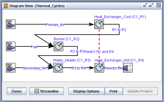
Similarly, to rename the inlet source entering the PSR #3 (now labeled Water_Heater), right-click on the C1_R3_INLET1 node on the project tree and select Rename. You can also right-click on an inlet source in the diagram itself and select Rename from the context menu that appears. Then enter Secondary_Air as the new label and click . Using these steps you can rename all of the Inlet Sources as well, as shown in Figure 2.36: Thermal_Cycle Diagram—All Connections Renamed. We will refer to these labels in the next sections. Click the button after the reactors and Inlet Sources are renamed.