


The CFX-Pre workspace contains a tree view as well as various details views that are used during the specification of mesh import, mesh transformation, physics, regions, materials, and expressions.
A powerful feature of CFX-Pre is automatic physics checking. Objects that contain inconsistent or incorrect settings are highlighted in red. Detailed error messages are shown in the physics validation summary window. For details, see Physics Message Window.
The Outline tree view displays a summary of the physics that have been defined for the simulation. The tree view window initially contains a default list of objects in a tree format.
The following topics are discussed in this section:
Tip: Typing Ctrl+F activates the search facility, which can be used to quickly locate an item in the tree. Note that the search is case-sensitive and that the text box disappears after a few seconds of inactivity.
When working with the tree view, note the following:
New objects are displayed in the tree as they are created.
Clicking any object that is applied to a region will highlight that region in the viewer when highlighting is enabled (that is, when the Highlighting icon
 is selected in the 3D Viewer toolbar). For
details, see 3D Viewer Toolbar.
is selected in the 3D Viewer toolbar). For
details, see 3D Viewer Toolbar.Objects shown in red contain incorrect physics definitions.
Right-click an object (or group selection of objects) to display the shortcut menu.
For details, see Outline Tree View Shortcut Menu Commands.
The Outline tab displays the tree view, which shows a summary of the current physics definition for a simulation. The tree structure displayed reflects the structure used in the CFX Command Language (CCL) for physics definition. You can select any object in the tree and double-click to gain direct access to the appropriate tab to edit its settings. You can also right-click an object and display the CCL definition of an object in the Command Editor dialog box, where it can be edited.
The remainder of this section describes the main areas in the Outline tree view.
- Mesh
Provides access to all mesh operations in CFX-Pre. This includes mesh import, mesh transformations, and the render/visibility properties of meshes in the viewer. Meshes generated in many other mesh generation packages can be imported into CFX-Pre. For details, see Importing and Transforming Meshes.
Meshes that have been glued together are listed under Connectivity in the tree view.
- Simulation
Enables you to define the one or more analyses of the simulation.
Optionally, you can open a copy of the Simulation branch in a separate tab.
- Analysis
Enables you to define and edit an analysis:
- Analysis Type
Enables the specification of an analysis as steady-state or transient, and whether it requires coupling to an external solver. For details, see Analysis Type.
- Domains
Enables you to define and edit the type, properties and region of the fluid, porous or solid. For details, see Domains, Boundary Conditions, Subdomains and Source Points.
- Domain Interfaces
Enables you to define and edit the method of connecting meshes or domains together. For details, see Domain Interfaces.
- Global Initialization
Enables you to set global initial conditions (across all domains). Domain specific initialization is set through the domain forms. For details, see Initialization.
- Solver
Enables the defining and editing of Setting the Solution Units, Solver Control, Solver: Expert Parameter, Output Control and Mesh Adaption.
- Coordinate Frames
Creates and edits coordinate frames. A Cartesian coordinate frame exists by default, but other Cartesian coordinate frames can be made. For details, see Coordinate Frames in the CFX-Solver Modeling Guide and Coordinate Frames.
- User Locations
Creates user locations, including user line, user point, user point cloud, and user surface. For details, see User Locations.
- Transformations
Creates and edits transformations that can be used for positioning data from a results file as part of initialization. For details, see Interpolation Mapping in the CFX-Solver Modeling Guide.
- Materials / Reactions
Creates, edits, and displays materials and reactions. Many different material types can be defined, edited or imported. Specialist materials and reactions can be imported from external files, such as the RGP (Real Gas Properties) file and Flamelet reaction files. For details, see Materials and Reactions.
- Expressions, Functions, and Variables
Used to create, edit, and plot: Additional Variables, expressions, user functions, user routines, GT-SUITE models. For details, refer to the following sections:
- Simulation Control
Enables you to set up the control of analyses in the simulation. This control is facilitated by defining and editing one or more configurations as well as global solver execution control. For more information, see Solve.
- Case Options
The Graphics Style, Labels and Markers, and General options enable you to override the defaults for the current simulation only — they will not be retained for future simulations. The default settings for CFX-Pre are set in the Edit > Options dialog box — these settings are retained and take effect when a new case is started. See CFX-Pre Options for a description of these settings.
- Extensions
Enables you to access to any customized extensions available to CFX-Pre. For details, see CFX-Pre Extensions Menu.
Right-clicking any object in the tree view displays a shortcut menu. Double-clicking an object performs the default action for that object. Shortcut menu command descriptions follow:
| Command | Description |
|---|---|
|
Configuration |
Simulation Control > Configurations > Insert > Configuration opens the Configuration Editor. |
|
Copy |
The Copy command is usually combined with Paste to quickly replicate objects. |
|
Define Connection |
Mesh > Define Connection opens the Mesh Connections Editor. |
|
Delete |
Deletes the selected object. The physics for the simulation are checked after objects are deleted. Objects containing invalid parameters are highlighted in red in the tree view. |
|
Delete All Mesh |
Deletes the mesh, but not the named areas in the Outline tree view. When this happens, the physics message window will show errors that say the named objects cannot be found. If you then import a new mesh that uses the same names for objects, the names will be resolved and the errors will disappear. |
|
Duplicate |
Copies the definition of the selected object to a new object. You will be required to enter a name for the duplicated object, which will then be created at the same level (that is, for a boundary condition, the new boundary will be created in the same domain as the initial object). |
|
Edit |
Opens the relevant tab where new parameters for the object can be entered. In most cases[a], you can also edit an object by double-clicking it in the tree view. |
|
Edit In Command Editor |
Opens the Command Editor dialog box and displays the CCL definition for the highlighted object. You can edit the CCL directly to change the object definition[a]. For details, see Command Editor Dialog Box. |
|
Expand/Collapse Sub-Branches |
Provides a fast way to navigate the tree view. |
|
Export CCL |
Opens the Export CCL dialog box, which is similar to the dialog box described in Export Region Data, below. |
|
Export CSV |
Opens the Export CSV dialog box. For details, see Export CSV Command. |
|
Export Region Data |
Opens the Export Region CCL dialog box, used to save the region data to a .ccl file. |
|
Glue Adjacent Meshes |
If there are multiple mesh assemblies that have matched meshes, you can use this option to try to glue them together. Select the assemblies in the tree view (while holding down the Ctrl key). Gluing can be useful to avoid setting up a GGI interface within a domain, but does require that the meshes match exactly on the surfaces that are to be glued. When you transform or copy multiple assemblies, each copy is not only glued to its original assembly or to other copies, but also to any other assemblies that are transformed or created. For more information, see Gluing Meshes Together. |
|
Hide |
Makes the active object invisible in the viewer. Hide has the same effect as clearing the check box next to an object in the tree view. |
|
Hide Interface Boundaries |
Hides the interface boundaries in the Outline tree view. |
|
Import CCL |
Opens the Import CCL dialog box, which is similar to the dialog box described in Import Region Data, below. |
|
Import Mesh |
Opens the Import Mesh dialog box. This is used to import a new mesh using an appropriate file. For details, see Importing Meshes. |
|
Import Library Data |
This command,
available from the |
|
Import Region Data |
Opens the Import Region CCL dialog box. This is used to load region data from a .ccl file. |
|
Insert |
Various objects are available for insertion, depending on which object is highlighted. All of the options available from this menu can also be accessed from the Insert menu. For details, see CFX-Pre Insert Menu. |
|
Mesh Statistics |
Opens the Mesh Statistics dialog box and provides
a detailed information about the active mesh. The Mesh Statistics
dialog box can be invoked for one or more assemblies and/or primitive
3D/2D regions. The data displayed includes the number of nodes,
elements, the number of each element type, and physical extents of
the mesh. The Note that for multiple selections, or for selections that consist of composite regions containing multiple primitive regions, the number of nodes and elements displayed is the sum of the number of nodes and elements in each of the underlying primitive regions. The sum takes no account of whether any nodes in the underlying primitive regions are common to two or more of the primitive regions in the selection. As a result, the number of nodes displayed may be higher than the number of nodes in the final mesh that is written to the CFX-Solver input file. In general, the number of nodes in the final mesh will depend on the physics definition, which affects whether nodes that are common to multiple primitive regions can be considered to be the same node. |
|
Paste |
The Paste command is available when you have already used the Copy command on an object. To avoid producing objects with the same name, you are prompted to provide a name when you paste the new object. For objects that contain a location parameter (such as domains and boundary conditions), you will usually need to edit the new object after pasting it to avoid multiple objects that reference the same location. If you are pasting a domain object, then you will need to edit each child object in the domain that references a location. For example, you will need to change the locations that boundary conditions reference so that they point to locations in the new domain. You can simply delete a default domain boundary in this situation; this will enable CFX-Pre to create a new default boundary for the domain that references the correct locations. |
|
Reload Mesh Files |
If any of the mesh regions become corrupted or are accidentally deleted, selecting Reload Mesh Files reloads all mesh files used in the simulation. This command cannot be used to insert a new mesh; do to so, select Import Mesh. For details, see Reload Mesh Files Command. Note: This command is not required (and is not available) in CFX-Pre launched from Ansys Workbench. |
|
Rename |
Changes the selected object’s name. |
|
Render |
Enables you to change the appearance of almost any object. For example, a boundary condition or domain interface can be displayed with a solid color, the transparency of a domain can be altered, and so on. |
|
Report Interface Summary |
Invokes a message box that shows a summary of the interfaces and their types. For details, see Mesh Connection Options in the CFX-Solver Modeling Guide. |
|
Show/Hide |
Makes the active object either visible (Show) or invisible (Hide) in the viewer. Show and Hide have the same respective effects as selecting and clearing the check box next to a specific object in the tree view. |
|
Show Interface Boundaries |
Shows the interface boundaries in the Outline tree view. |
|
Start Solver |
Enables you to access the Define Run, Run Solver, and Run Solver and Monitor commands. These commands are also available from the main toolbar. |
|
Transform Mesh |
Opens the Mesh Transformation Editor dialog box, enabling you to modify the location of the active mesh through rotation, translation, or reflection. The mesh can also be resized using a scaling method. For details, see Transform Mesh Command. |
|
Use as Workbench Input Parameter |
Available when an expression is selected, this command allows the expression to be used as a workbench input parameter. |
|
View By |
This command, available for the |
|
View in New Tab |
Simulation > View in New Tab enables you to view a copy of the contents of the Simulation branch in a separate tab. |
|
View in CFD-Post |
Prompts you to save a CFX-Solver Input file, then automatically starts CFD-Post with that file loaded. |
|
Write Solver Input File |
Has
the same effect as clicking Write Solver Input File |

[a] An expression that is set as an input parameter in Ansys Workbench cannot be edited in CFX-Pre or CFD-Post (as the results of such edits are not passed to Ansys Workbench) and will be grayed out. However, the expression can be declared to no longer be an input parameter or it can be deleted.
Details view is a generic term for the editor pane that opens when you edit an object of the Outline tree view. A details view appears on a tab beside the Outline tab. Each details view presents the settings and controls that define an object.
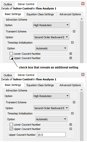
Some check boxes reveal additional settings when selected. In the example above, selecting the Upper Courant Number check box makes it possible to see and override the default value; the white background of the field indicates that you can edit the value shown.
Most CFX-Pre settings have default values that will enable you to define an object or set a control as easily as possible. If there is a setting that requires you to set a value, basic physics checking occurs when you click or on a details view and most missing settings are detected then. Complete physics checking takes place when you attempt to write a solver file and all missing settings are detected and reported at that time.
You use the details view to define the properties of an object. The details view contains one or more tabs, depending on the type of object being defined.
Many properties can be set via a CEL expression. To enter an expression:
Click in the field for a property.
Click the Enter Expression icon that appears beside the field. This enables the field to accept an expression name.
Either enter an expression definition directly, or type the name of an existing expression. You must ensure that the expression evaluates to a value having appropriate units for the property that uses the expression.
For details on CEL expressions, see Expressions.
For CFX components in Ansys Workbench, any CEL expression can be made into a parameterized CEL expression by defining it as a Workbench input parameter. You can do this by creating an expression and parameterize it by right-clicking it in the Expression editor. You can then use that expression as the value of a property.
You can stop a property from being specified as a Workbench input parameter. However, the corresponding CEL expression persists and can be managed by the Expression editor.
A property that accepts only an integer value (but not a CEL
expression) is also capable of being controlled by a Workbench input
parameter. For such a property, the Set to Workbench input
parameter  and Set to value
  icons are used to toggle the value between being
a Workbench input parameter or not.
icons are used to toggle the value between being
a Workbench input parameter or not.