


The wall interaction option is available in CFX-Pre for simulations involving Lagrangian particles or when a particle user routine has been created. The wall-interaction options available in Ansys CFX are outlined below:
This is the default particle-wall interaction model in Ansys CFX, typically
controlled by setting the wall interaction mode to Equation
Dependent in CFX-Pre. With this model, the droplet is
reflected off a wall and the momentum change across the collision is
described using the perpendicular and parallel coefficients of restitution.
For details, see Fluid Values for Walls in the CFX-Pre User's Guide.
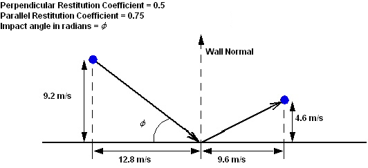
The parallel and perpendicular restitution coefficients describe the action of particles when they hit a wall. Enter a numerical quantity or CEL based time-dependent expression to specify the value of restitution coefficients. Coefficient values of 1 described an elastic collision, while values less than 1 describe an inelastic collision. Figure 8.3: Particle Track Behavior at a Wall Boundary shows an example of a particle velocity before and after impacting a wall when the perpendicular restitution coefficient is 0.5 and the parallel restitution coefficient is 0.75.
The parallel coefficient will almost always be 1. The perpendicular coefficient will depend on the particle material. Particles that bounce off walls will have a perpendicular coefficient close to 1, while particles that stick to walls (for example, water droplets) will have a perpendicular coefficient of 0.
If you want to terminate tracking of particles when they hit a wall boundary, then you can set both coefficients to zero. Although it should be noted that when a particle hits a wall and the perpendicular coefficient of restitution is set to zero then the particle comes to a stop regardless of what is set for the parallel coefficient of restitution
Important: In case of a moving wall, the coefficients need to consider the velocity of the wall. This means the relevant coordinate system must always be the wall and the relative particle velocity (with respect to the wall) has to be taken into account if either of the coefficients are smaller than 1.
Note: Setting the perpendicular coefficient of restitution to a small positive number is not a valid way to simulate particle sliding along a wall. Currently there is no method for accurately simulating this type of particle sliding.
The change in momentum of particles due to the action at a wall results in a force on the wall.
The following models available in Ansys CFX enable the simulation of wall film formation by particles being deposited at a wall, as well as the resulting interaction of particles with the film covered wall.
Elsaesser particle-wall interaction model
Stick-to-wall model
User Defined Wall Film Modeling
For details, see Particle-Wall Interaction in the CFX-Solver Theory Guide.
Particle-wall interactions involve complex physics, especially in the presence of a wall film. The available models may not suit certain cases. Therefore a User Fortran interface has been made available to enable you to use your own models in order to define the creation of a wall film. The following example illustrates how this can be done.
This is an example of a basic routine that can be used to calculate the particle-wall interaction, enabling the generation of a particle wall film. The model uses a "child generation" model (i.e. a droplet can split into several "child" droplets). In this example, a particle impacting the wall may either be fully deposited at the wall or it will break up ("splash") into two parts ("children"): one being reflected and the other one being deposited at the wall.
In this example, the splashing criteria is solely based on the impact details of the particle, such as the impact angle and momentum.
The input arguments for the routine are:
Wall impact angle
Particle velocity components
Particle diameter
Particle number rate
Fluid density at particle position
The return variables of the user routines are:
"Breakup indicator"
Particle diameter after wall interaction
Particle number rate after wall interaction
Normal coefficient of restitution of particle
Parallel coefficient of restitution of particle
Particle mode
The User Defined Wall Film Interaction model supports the following combinations of return variables:
Child Droplet ModeThis is a required return variable. It currently holds two values:
__regular_particle__(integer value of1)__wall_particle__(integer value of20)
Child Droplet Breakup IndicatorThis is a required return variable that is used by the particle tracker to determine the number of child droplets created. It can be set to a real array with a value of either
1or0. If set to0, then any child data returned to the tracker is ignored.Child Droplet DiameterThis is a real array that holds the child droplet diameter values.
Or
Child Droplet Diameter RatioThis is a real array that holds the child droplet diameters’ ratios (
diameter_childdivided bydiameter_parent).Child Droplet Diameter RatioThis is a real array that holds the child droplet number rates.
Child Droplet VelocityThis is a real array that holds the values of the child droplet velocity components.
Or
Child Droplet Perpendicular Coefficient of
                                        Restitution
Real array that holds the child droplet normal coefficient of restitution (used to determine the velocity components of child droplets).
Child Droplet Parallel Coefficient of
                                        Restitution
This is a real array that holds child droplet parallel coefficients of restitution (which are used to determine the velocity components of child droplets)
Note that a maximum of 4 child droplets may be generated with the "child generation" model.
You can copy the routine pt_wall_splash.F from
the examples\UserFortran directory, which is
under the installation directory.
The Fortran code for this example is:
#include "cfx5ext.h"
dllexport(pt_wall_splash)
      SUBROUTINE PT_WALL_SPLASH (NLOC,NRET,NARG,RET,ARG,CRESLT,
     &                           CZ,DZ,IZ,LZ,RZ)
CC
CD User routine: template for particle user routine
CC
CC --------------------
CC        Input
CC --------------------
CC
CC  NLOC   - number of entities
CC  NRET   - length of return stack
CC  NARG   - length of argument stack
CC  ARG    - argument values
CC
CC --------------------
CC      Modified
CC --------------------
CC
CC --------------------
CC        Output
CC --------------------
CC
CC  RET    - return values
CC
CC --------------------
CC       Details
CC --------------------
CC
CC======================================================================
C
C ------------------------------
C     Preprocessor includes
C ------------------------------
C
#include "cfd_sysdep.h"
#include "cfd_constants.h"
C
C ------------------------------
C        Argument list
C ------------------------------
C
      INTEGER NARG, NRET, NLOC
C
      CHARACTER*(4) CRESLT
C
      REAL ARG(NLOC,NARG), RET(NLOC,NRET)
C
      INTEGER IZ(*)
      CHARACTER CZ(*)*(1)
      DOUBLE PRECISION DZ(*)
      LOGICAL LZ(*)
      REAL RZ(*)
C
C=======================================================================
C
C ---------------------------
C    Executable Statements
C ---------------------------
C
C=======================================================================
C
C     Return variables:
C     -----------------
C
C     Child droplet breakup indicator                       : RET(1,1)
C     Child droplet diameter                                : RET(1,5)
C     Child droplet number rate                             : RET(1,9)
C     Child droplet normal coef of restitution              : RET(1,13)
C     Child droplet parallel coef of restitution            : RET(1,17)
C     Child droplet mode                                    : RET(1,21)
C
C     Argument variables
C     -------------------
C
C     Particle impact angle                                : ARG(1,1)
C     Particle velocity                                    : ARG(1,2)
C     Particle diameter                                    : ARG(1,5)
C     Particle number rate                                 : ARG(1,6)
C     Fluid density                                        : ARG(1,7)
C
C     We know that NLOC is 1 for the particle user source routines!!!!
C=======================================================================
C
C-----------------------------------------------------------------------
C     Calculate the return variables
C-----------------------------------------------------------------------
C
      CALL SPLASH (RET(1,1),RET(1,5),RET(1,9),RET(1,13),RET(1,17),
     &             RET(1,21),ARG(1,1),ARG(1,2),ARG(1,5),ARG(1,6),
     &             ARG(1,7))
C
      END
C
      SUBROUTINE SPLASH (BRKUP_IND,CHILD_DIAM,CHILD_NRATE,
     &                   CHILD_COEF_N,CHILD_COEF_P,CHILD_MODE,
     &                   ANGLE,VEL_PT,DIAM_PT,NRATE_PT,DENS_FL)
C
C ---------------------------
C    Preprocessor includes
C ---------------------------
C
#include "cfd_sysdep.h"
#include "cfd_constants.h"
C
C---- Do not change these defines, they have to be consistent with what
C     the solver uses
C
#define   __regular_particle__ 1
#define      __wall_particle__ 20
#define     __pt_uf_get_data__ 1
#define    __pt_uf_save_data__ 2
#define        __pt_uf_iseed__ 1
#define        __pt_uf_pmode__ 2
C
C ------------------------------
C        Argument list
C ------------------------------
C
      REAL   FACT, ANGLE, VEL_PT(3), DIAM_PT, NRATE_PT,
     &       BRKUP_IND(3), CHILD_DIAM(3), CHILD_NRATE(3),
     &       CHILD_COEF_N(3), CHILD_COEF_P(3), CHILD_MODE(3), DENS_FL
C
C ------------------------------
C        Local variables
C ------------------------------
C
      REAL    SIGMA, VISC_PT, R, SPEED_PT, ANGLE_DEG, ALFA, BETA,
     &        GAMMA, VEL_NORM, OH, RE, K, M1M0
      INTEGER ICHILD, ISEED, ACTION
C
C ------------------------------
C    Executable statements
C ------------------------------
C
C=======================================================================
C     Prologue
C=======================================================================
C
C---- Initialization
C
      ICHILD = 0
C
C---- Get particle seed info (needed for random number generator)
C
      ACTION = __pt_uf_save_data__
      CALL USER_PARTICLE_INFO(ACTION,__pt_uf_iseed__,ISEED)
C
C---- Some material properties (water)
C     --> Surface tension coefficient
C     --> Particle viscosity
C
      SIGMA   = 0.0201
      VISC_PT = 0.001
C
C---- Random number (required for deviation angle)
C
      CALL GET_RANDOM(R,1,ISEED)
C
C=======================================================================
C     Computation Section
C=======================================================================
C
C---- Particle velocity magnitude and impact angle
C
      SPEED_PT  = SQRT(VEL_PT(1)**2 + VEL_PT(2)**2 + VEL_PT(3)**2)
      ANGLE_DEG = ANGLE*180./PI
C
C---- Ohnesorge and Reynolds number
C     --> Re, based on wall normal impact velocity!
C
      VEL_NORM = SIN(ANGLE)*SPEED_PT
      OH = VISC_PT/SQRT(DENS_FL*DIAM_PT*SIGMA)
      RE = DENS_FL*DIAM_PT*VEL_NORM/VISC_PT
C
C-----------------------------------------------------------------------
C     Precompute reflection angle
C-----------------------------------------------------------------------
C
C---- Impact angle, ALFA, average reflection angle, BETA. Add random
C     deviation angle, GAMMA, if ALFA < 15 deg.
C
      ALFA  = 90.   - ANGLE_DEG
      BETA  = 61.88 + 0.326*ALFA
      GAMMA = 17.6  - 0.18*ALFA
C
      IF (ALFA .LT. 15.) BETA = BETA + (R-0.5)*GAMMA
C
C---- Compute K-value
C     --> Clip K to avoid overflow during m1/m0 calculation
C         (221^9.2133 = 3.9773E+21)
C
      K = MIN(OH*RE**1.25,221.)
C
C-----------------------------------------------------------------------
C     K <= 57 -> Particle deposited at wall
C-----------------------------------------------------------------------
C
      IF (K .LE. 57) THEN
C
        ICHILD = ICHILD + 1
        BRKUP_IND(ICHILD)    = 1.
        CHILD_DIAM(ICHILD)   = DIAM_PT
        CHILD_NRATE(ICHILD)  = NRATE_PT
        CHILD_COEF_N(ICHILD) = 0.0
        CHILD_COEF_P(ICHILD) = 0.0
        CHILD_MODE(ICHILD)   = __wall_particle__
C
C-----------------------------------------------------------------------
C     ... else partially reflected
C-----------------------------------------------------------------------
C
      ELSE
C
C---- Mass fraction across reflection
C
        M1M0 = 3.9869E-21*K**9.2133
C
C---- Reflected portion of particle
C
        ICHILD = ICHILD + 1
        BRKUP_IND(ICHILD)    = 1.
        CHILD_DIAM(ICHILD)   = DIAM_PT*M1M0
        CHILD_NRATE(ICHILD)  = NRATE_PT
        CHILD_COEF_N(ICHILD) = COS(BETA*PI/180.)*SPEED_PT
        CHILD_COEF_P(ICHILD) = SIN(BETA*PI/180.)*SPEED_PT
        CHILD_MODE(ICHILD)   = __regular_particle__
C
C---- Deposited portion of particle
C
        ICHILD = ICHILD + 1
        BRKUP_IND(ICHILD)    = 1.
        CHILD_DIAM(ICHILD)   = DIAM_PT*(1. - M1M0)
        CHILD_NRATE(ICHILD)  = NRATE_PT
        CHILD_COEF_N(ICHILD) = 0.0
        CHILD_COEF_P(ICHILD) = 0.0
        CHILD_MODE(ICHILD)   = __wall_particle__
C
      ENDIF
C
C=======================================================================
C     Epilogue
C=======================================================================
C
C---- Update ISEED in particle database with value computed in
C     this routine
C
      ACTION = __pt_uf_get_data__
      CALL USER_PARTICLE_INFO(ACTION,__pt_uf_iseed__,ISEED)
C
      END
The user-defined particle-wall interaction model can be used to model such
quantities as restitution coefficient, mass flow absorption, erosion and
particle breakup using a Fortran routine. The Fortran routine should first
be written, and a shared library created. For details, see Creating the Shared Libraries. After this step, you should create a User Routine
of type Particle User Routine. For details, see Particle User Routines in the CFX-Pre User's Guide.
Input arguments to the subroutine can be any valid variables (selected from the Arguments drop-down list in CFX-Pre).
The returned quantities must be made up of one or more of the following:
Perpendicular / Parallel Coefficient of Restitution
Mass Flow Absorption Coefficient
Particle Erosion (the returned erosive wear is assumed to be non-dimensional, e.g. grams of eroded material per gram of colliding particles)
Particle Breakup Factor (the number rate of a particle is increased by the breakup factor, and the diameter is reduced by the cube root of the breakup factor)
In the
<install_dir>\examples\UserFortran
directory, you can find a wall-interaction particle routine,
pt_breakup_wall.F, and corresponding
CCL template, pt_breakup_wall.ccl.
The erosion model can be set on a per-boundary or per-domain basis. When selected for the domain, the domain settings will apply for all boundaries that do not explicitly have erosion model settings applied to them. To override the domain setting, turn-on the Erosion Model. Additional information on erosion is available. For details, see:
The rough wall model can be set on a per-boundary or per-domain basis. When selected for the domain, the domain settings will apply for all boundaries that do not explicitly have rough wall model settings applied to them. To override the domain setting, turn on the Rough Wall model on the corresponding patches. Additional information on rough wall treatment is available in Particle-Rough Wall Model (Virtual Wall Model) and The Sommerfeld-Frank Rough Wall Model (Particle Rough Wall Model) in the CFX-Solver Theory Guide.
To simulate the breakup of particles due to aerodynamic forces, five different interior breakup models are available: Reitz & Diwakar, TAB, ETAB, CAB and Schmehl model. See Spray Breakup Models in the CFX-Solver Theory Guide for information on these models.
The mass flow absorption is available to enable a fraction of particles to leave the domain when they collide with a wall. For each particle tracked, the mass flow (number) rate is reduced whenever it strikes a wall.
Particles can be injected through walls in the same way as they are injected through inlets. For details, see Mass and Momentum.
The impact angle  is the angle between the approaching
particle track and the wall. It is measured in radians. See Figure 8.3: Particle Track Behavior at a Wall Boundary.
is the angle between the approaching
particle track and the wall. It is measured in radians. See Figure 8.3: Particle Track Behavior at a Wall Boundary.
The particle injection positions on a wall are defined in the same way as at inlets. For details, see Particle Position.
The diameter distribution on a wall is described in the same way as for a domain. For details, see Particle Diameter Distribution.
The particle mass flow rate through a wall is defined in the same way as through inlets. For details, see Particle Mass Flow Rate.