


You can introduce particles into the domain by enabling the Define Particle Behavior toggle on the Fluid Values form and specifying their properties on an inflow or opening boundary. This is used when you have more than one inlet, but particles only enter through some of them. The particle velocity, injection position, diameter distribution, and mass flow rate need to be specified. For details, see Fluid Values for Inlets and Openings in the CFX-Pre User's Guide.
The Normal Speed, Cartesian Velocity
Components, and Cylindrical Velocity
Components are described at Mass and Momentum.
The Zero Slip Velocity option causes the particles to be
injected at the local velocity of the continuous phase. It can be used at an
inflow boundary that is specified using a mass flow or pressure option for the
continuous phase.
This option produces a random injection over the entire inlet. For details, see Number of Positions.
This option restricts the injection location to an annular region on the boundary condition. The annulus is defined by an axis, as well as a distance from the axis for both the inner and outer radii of the annulus.
The annulus is assumed to be infinitely long in both the positive and negative directions of its axis, which is defined by the two specified points. Particles will be injected through any portion of the boundary region intersecting the infinite annulus. If there is no overlapping region between the boundary region and the projection of the annulus onto the boundary region, then no particles will be injected.
A description of the format used to enter the First and Second Point of Axis is available in:
The First and Second Line Point for Normal Distribution define the end points of the line. A description of the format used to enter the first and second point of axis is available in Point Data Format. It is expected that the line lies in the plane of the injection boundary. The injection weighting is a normal distribution around the line, with the Standard Deviation for Normal Distribution determining the shape of the distribution. For details, see Number of Positions.
This option weights the injection location towards a point. It is expected that the point lies in the plane of the injection boundary. A normal distribution is used to determine the probability of injection as you move away from the point, using the Standard Deviation for Normal Distribution. A description of the format used to enter the Center Point for Normal Distribution is available in:
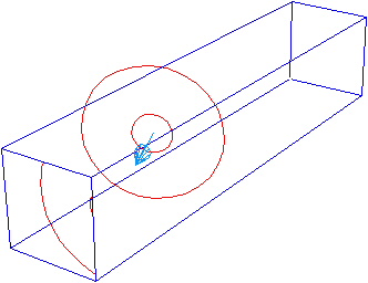
The Center Point for Normal Distribution and Distance From Center Point define the center and radius of the circle, which is expected to lie in the plane of the injection boundary. A description of the format used to enter the center point is available in Point Data Format.
The injection weighting follows the circumference of the circle (that is, there is a lower probability of injecting particles at the center of the circle). The Standard Deviation for Normal Distribution determines the shape of the normal distribution as you move away from the circumference of the circle. For details, see Number of Positions.
The Face Weighting Factor is a dimensionless number
that sets a weighting factor between 0 and 1 for each location on the
injection boundary. It is expected to be a defined by a function of x, y,
and/or z using either a CEL expression or a User CEL
Function. For details, see Number of Positions.
Particles are injected at the center of each element face. An illustration of the location of face centers is available in Discretization of the Governing Equations in the CFX-Solver Theory Guide.
Particles are injected at the integration points for each face. An illustration of the location of integration points is available in Discretization of the Governing Equations in the CFX-Solver Theory Guide.
For each particle type, you must specify the number of representative particles injected at a boundary condition or particle injection region.
For steady-state simulations, the Number of Positions parameter sets the total number of particles to be injected. You can specify the number directly or proportional to the injected mass flow rate. In the latter case, you must specify the number of particles per unit mass flow.
For transient simulations, you must specify the number of injected particles per unit time. You can specify the number directly or proportional to the injected mass flow rate. In the latter case, you must specify the number of particles per unit time and the mass flow rate. In a transient simulation you can specify the number of particles or mass flow rate as an expression in time.
Note: For user defined injections with the number of particles being a function of the injected mass flow rate, you must specify the mass flow rate in the CCL and not in a user routine. This applies to steady-state simulations, as well as to transient simulations.
When choosing the number of particles, you should remember that the modeled particles are a representative sample of the actual particles and the number of particles modeled will be much smaller than the real number of particles (for details, see Particle Number Rate). The specified Particle Mass Flow rate accounts for the fact that a smaller number of particles are modeled than really exist. The size and location on the boundary of the modeled particles is determined randomly (but can be weighted using a particular distribution).
The appropriate number of injected particles to be used in a simulation cannot be easily determined. This number strongly depends on several parameters such as the fluid grid size or the distribution of the particles in the domain. The area of influence of the particles in the fluid phase must be covered by enough particles per element. The number of injected particles must be varied in order to see if the number is sufficiently large, as done in grid refinement studies.
Some of the options described above require point data to be entered. The
format used for this in CFX-Pre should be a comma separated list
corresponding to the x, y, and z coordinates, for example,
0,0,-0.1, with the units selected from the
drop-down list. If an expression is used, then the format will be similar to
0[m], 0[m], -0.1[m];
that is, with a unit specified for each coordinate.
By default, particles are injected randomly within the location constraints
which are set under the Particle Position option. To
enforce an equal spatial distribution, you can set the Particle
Locations option to Equally Spaced.
This option applies to domains and boundaries. When specified for boundaries, the settings applied override the domain values. For details, see Particle Diameter Distribution.
Specify the mass flow rate that is shared among all particles. This should be the total mass flow rate of particles through this boundary.
This need not be specified for one-way coupled particles if you are only interested in the particle tracks and not in derived quantities, such as particle volume fraction and forces on walls. It is always required for fully coupled particles.
The overall mass flow rate of the particles is shared among the representative particles being tracked. By dividing by the (initial) mass of the particle, this means that each representative particle has a Particle Number Rate. This quantity is used internally in the code for calculating overall sources to the continuous phase, and is also used in postprocessing for calculating mass flows of particles through boundaries, forces on walls, and so on.
Note: When expert parameter pt force export massflow is set to 't', particle
mass flows are always written to the results files. Otherwise they
will only be written if they are used in CEL expressions or monitors. For details, see Particle Tracking Parameters.
The static temperature is required for particle phases when a heat transfer model has been selected for the particles.
This section of the form becomes available when a variable composition mixture has been used to define the particles. Mass fractions are required for each of the species in the particle phase, and must sum to unity on all boundaries.