


A Volume is a collection of mesh elements that can be used as a locator for graphic objects or calculations. Volumes will not be displayed as perfect shapes (for example, a perfect sphere) because mesh elements are either included in or excluded from the Volume object.
The following characteristics of volumes will be discussed:
Note: There are several ways to insert a volume:
From the menu bar, select Insert > Location > Volume.
From the toolbar, select Location > Volume.
Depending on the context, you may be able to perform an insert from the shortcut menu in the tree view or in the 3D Viewer.
For details, see Domains.
The Element Types setting has the following options:
| Option | Description |
|---|---|
|
| Displays volume that is connected to a tetrahedral mesh. |
|
| Displays volume that is connected to a pyramid-shaped mesh. |
|
| Displays volume that is connected to a wedge-shaped mesh. |
|
| Displays volume that is connected to a hexagonal mesh. |
The Method setting has the following options:
Point is available only if the Sphere option is selected. The Point setting specifies a center point for the sphere volume. The point
can be anywhere in 3D space.
Radius is available only if the Sphere option is selected. The Sphere setting specifies a radius for the sphere volume.
Location is available only if the From Surface option is selected. The Location setting selects from a list of valid locations for the volume to
exist on.
Variable is available only if the Isovolume option is selected. The Variable setting selects a variable to plot the volume on. A Value for the variable must be selected before the volume can be defined.
These options are available only if the Isovolume option is selected. For help on which field to select, see Hybrid and Conservative Variable Values.
The Mode setting has the following options:
| Option | Description |
|---|---|
|
|
Creates a volume at the specified
radius for the |
|
|
Creates a volume for all of the radii less than
the specified radius for the |
|
|
Opposite to the |
The Mode setting has the following options:
| Option | Description |
|---|---|
|
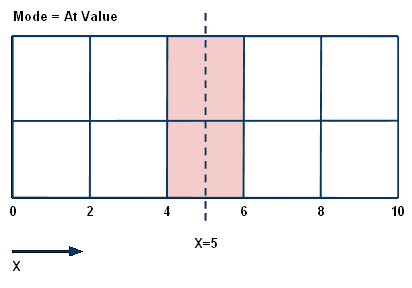
| Creates a volume for all the mesh elements in the domain equal to the entered value. |
|
| Creates a volume for all the mesh elements in the domain above the entered value. |
|
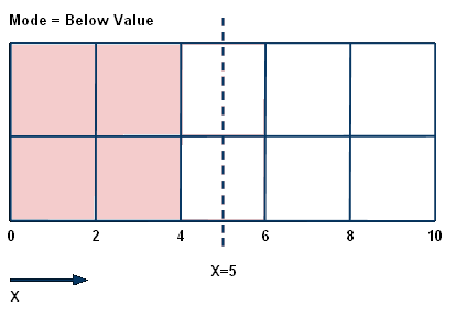
| Creates a volume for all the mesh elements in the domain less than the entered value. |
|
| Creates a volume for all the mesh elements in the domain in between the two entered values. |
The Value fields are available only if
the Isovolume option is selected. The Value fields specify values to compare to using the Mode options. For example, if Value is set to 2 and Mode is
set to At Value, the Volume will plot where the
variable is equal to 2.
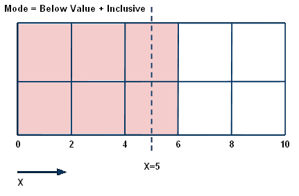
Select the Inclusive check box to add the
entered values to an above or below comparison Mode. For example, if the Inclusive check box is
selected with the Below Intersection option,
the volume will include the radius entered or surface selected.
In order to see the effects of the Inclusive check box on the Minimum Face Angle variable set to the Below Value mode, do the following:
Open a results file.
Create a volume, accepting the default name.
Set Variable to Minimum Face Angle, Mode to Below Value, and then click . Few volumes appear.
Now enable Inclusive and click again. Many more volumes appear.
The differences you see are caused by how CFD-Post calculates values for a given point on a mesh (Mode is set to At Value):
...as compared to Mode being set to Below Value
...and as compared to Mode being set to Below Value with Inclusive being selected:
Remove Internal Faces is on by default, causing CFD-Post to remove all internal mesh element faces from a volume object. Turning off this setting can save significant rendering time by skipping the removal process. As a side effect of turning off this setting, internal faces can appear in a volume object that is transparent or clipped.
Note: It is a known issue that some mesh faces might be missing in the 3D Viewer when Remove Internal Faces is off. This issue seems more likely to occur if the object being displayed contains many elements and involves more than one element type.
The color settings can be changed by clicking the Color tab. For details, see Color Tab.
The rendering settings can be changed by clicking the Render tab. For details, see Render Tab.
The View tab is used for creating or applying predefined Instance Transforms for a wide variety of objects.
For details on changing the view settings, see View Tab.