


A plane is a two-dimensional area that exists only within the boundaries of the computational domain.
The following characteristics of planes will be discussed:
Note: There are several ways to insert a plane:
From the menu bar, select Insert > Location > Plane.
From the toolbar, select Location > Plane.
Depending on the context, you may be able to perform an insert from the shortcut menu in the tree view or in the 3D Viewer.
For details, see Domains.
The Method setting has the following options:
| Option | Description |
|---|---|
|
|
Defines a plane normal to the X axis. |
|
|
Defines a plane normal to the Y axis. |
|
|
Defines a plane normal to the Z axis. |
|
|
Enables you to specify a point on the plane and a normal vector to the plane. |
|
|
Enables you to define a plane by providing three points that lie in the plane. |
X is available only if the YZ
Plane option is selected. The X setting
specifies an offset value from the X axis.
Y is available only if the ZX
Plane option is selected. The Y setting
specifies an offset value from the Y axis.
Z is available only if the XY
Plane option is selected. The Z setting
specifies an offset value from the Z axis.
Point is available only if the Point and Normal option is selected. The Point setting specifies the 3D coordinates of the point that lies on the
plane.
Normal is available only if the Point and Normal option is selected. The plane normal
is calculated as a vector from the origin to the specified coordinates.
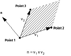
These options are only available if the Three Points option is selected. The Point 1, Point 2, and Point 3 settings specify
three points that lie on the plane.
The normal vector to the plane is calculated using the right-hand rule. The first vector is from Point 1 to Point 2, and the second is from Point 1 to Point 3, as shown in the following diagram. For example, the direction of this vector might be important if you are using the plane to define a Clip Plane.
The Type setting has the following options:
| Option | Description |
|---|---|
|
|
Cuts through a complete cross-section of each domain specified in the Domains list. A slice plane is bounded only by the limits of the domain. The Plane Type must be set to Slice for this option (default). |
|
|
Causes the boundary of the plane to be in the shape of a circle. The circle is centered at the origin for the YZ, ZX, and XY Planes. For the other two methods, the circle is centered at the first point entered in the Definition frame. |
|
|
Causes the boundary of the plane to be a rectangular shape. The rectangle is centered at the origin for the YZ, ZX, and XY Planes. For the other two methods, the rectangle is centered at the first point entered in the Definition frame. |
Radius is available only if the Circular option is selected. The Radius setting specifies a radius for the circular boundary. You can enter
a value or select the Expression  icon to the right of the Radius setting to specify the radius as an expression.
These settings are available only if the Rectangular option is selected. Two of these options will be displayed because
a plane is a 2D object. These settings will specify a width and height
for the rectangular boundary. The size of the rectangle is determined
with reference to the planes origin (that is, the plane is resized
around its center).
This setting is available only if the Rectangular option is selected. Only one of these settings is displayed at once.
This setting specifies an angle to rotate the plane counterclockwise
about its normal vector by the specified number of degrees.
Invert Plane Bound is available only if
the Circular or the Rectangular option is selected. If this check box is selected, the area defined
by the rectangle or circle is used as a cut-out area from a slice
plane that is bounded only by the domains. The area inside the bounds
of the rectangle or circle do not form part of the plane, but everything
on the slice plane outside of these bounds is included.
Select the Slice option to cut the plane so that it lies only inside the domain.
A slice plane differs from a sampling plane. A sampling plane is a set of evenly-spaced sampling points that are independent of the mesh. When you create a slice plane, the sampling points are placed at locations where the slice plane intersects an edge of the mesh, causing an uneven distribution of the sampling points. The density of these sampling points in a slice plane is related to the length scale of the mesh.
When you use the slice plane for Vector plots, the seeds are the points where the plane intersects a point on the edge of three mesh elements. You can view the seeds by turning on the Show Mesh Lines option on the Render tab for the plane.
Select the Sample option to specify the amount of seeds in the plane.
When creating a sampling plane, the Plane Bounds must be either Circular or Rectangular. For the Circular option, the density of sampling
points is determined by the radius of the plane specified in the Plane Bounds tab and the number of radial and circumferential
sampling points. For Rectangular bounds, you
must specify the size of the bounds for your plane in each of the
plane directions. The density of sampling points depends on the size
of the plane and the number of samples in each of the two coordinate
directions that describe the plane.
Certain types of plots will show small differences across GGI interfaces. This is to be expected when the nodes of the computational grids on each side of a GGI connection do not match. For example, contour lines or fringe lines may not match exactly across a GGI interface. This is a very minor effect and is not an indicator of any problem.
For details, see Line Translation Using Picking Mode.
The color settings can be changed by clicking the Color tab. For details, see Color Tab.
The rendering settings can be changed by clicking the Render tab. For details, see Render Tab.
The View tab is used for creating or applying predefined Instance Transforms for a wide variety of objects.
For details on changing the view settings, see View Tab.