


VM-NR1677-02-4-a
VM-NR1677-02-4-a
NUREG/CR-1677: Volume 2, Benchmark Problem No. 4
Overview
| Reference: | NUREG/CR-1677 Volume II Piping Benchmark Problems, Dynamic Analysis Independent Support Motion Response Spectrum Method, P. Bezler, M. Subudhi & M. Hartzman of Brookhaven National Laboratory, prepared for the U.S. Nuclear Regulatory Commission, August 1985, Problem 1, pages 244-445 |
| Analysis Type(s): | |
| Element Type(s): | |
| Input Listing: |
Test Case
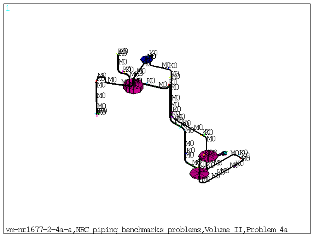
This benchmark problem is a three-branch, three-anchor piping subsystem from an actual nuclear power plant. The system configuration is shown in Figure 629: FE Model of the Benchmark Problem. The boundary or spring support elements ranged in stiffness from relatively soft to virtually rigid. Modal and response spectrum analysis is performed on the piping model. The input excitation consisted of four different excitation spectra sets developed for the actual system and show variations for elevation and extent. Each solution had a fifty natural frequency approximation with various spectra and spectrum weighting factors.
Response spectrum solutions are done for two cases:
Case 1: Envelope spectrum excitation
Case 2: Independent support excitation with absolute sum combination.
Frequencies obtained from modal solve and the nodal/element solution obtained from spectrum solve are compared against reference results.
| Material Properties | Geometric Properties | Loading | ||||||||||||||||||||||||||||||||||||||||||||||||||||||||||||||||||||||||||||||||||||||||||||||||||||||||||||||||||||||||||||||||||
|---|---|---|---|---|---|---|---|---|---|---|---|---|---|---|---|---|---|---|---|---|---|---|---|---|---|---|---|---|---|---|---|---|---|---|---|---|---|---|---|---|---|---|---|---|---|---|---|---|---|---|---|---|---|---|---|---|---|---|---|---|---|---|---|---|---|---|---|---|---|---|---|---|---|---|---|---|---|---|---|---|---|---|---|---|---|---|---|---|---|---|---|---|---|---|---|---|---|---|---|---|---|---|---|---|---|---|---|---|---|---|---|---|---|---|---|---|---|---|---|---|---|---|---|---|---|---|---|---|---|---|---|---|
Pipe Elements:
Stiffness for Spring-Damper Elements (lb/in): Since there are multiple Spring Supports at different locations, the Stiffness for Spring Damper Elements are listed based on the real constant set number. Set 48:
Set 49:
Set 50:
Set 51:
Set 52:
Set 53:
Set 55:
Set 58:
Set 60:
Set 62:
Set 63:
Set 64:
Set 65:
Set 66:
Set 67:
Set 68:
Set 70:
Set 72:
Set 75:
Set 76:
Set 77:
Set 79:
Set 80:
Set 81:
Set 82:
Set 83:
Mass Elements (lb-sec2/in): (Isotropic Mass) Set 23:
Set 24:
Set 25:
Set 26:
Set 27:
Set 28:
Set 29:
Set 30:
Set 31:
Set 32:
Set 33:
Set 34:
Set 35:
Set 36:
Set 37:
Set 38:
Set 39:
Set 40:
Set 41:
Set 42:
Set 43:
Set 44:
Set 45:
Set 46:
Set 47:
| Straight Pipe: Set 1:
Set 2:
Set 3:
Set 4:
Set 5:
Set 6:
Set 7:
Set 8:
Set 9:
Set 10:
Set 11:
Set 12:
Set 13:
Bend Pipe Elements: Set 14:
Set 15:
Set 16:
Set 17:
Set 18:
Set 19:
Set 20:
Set 21:
Set 22:
| Case 1: Case 2: |
Results Comparison
Table 85: Frequencies Obtained from Modal Solution
| Mode | Target | Mechanial APDL | Ratio |
|---|---|---|---|
| 1 | 2.612 | 2.610 | 1.000 |
| 2 | 2.914 | 2.914 | 1.000 |
| 3 | 4.337 | 4.336 | 1.000 |
| 4 | 4.660 | 4.660 | 1.000 |
| 5 | 5.734 | 5.723 | 1.000 |
| 6 | 5.833 | 5.832 | 1.000 |
| 7 | 7.359 | 7.358 | 1.000 |
| 8 | 7.769 | 7.768 | 1.000 |
| 9 | 9.952 | 9.956 | 1.000 |
| 10 | 10.329 | 10.327 | 1.000 |
| 11 | 10.679 | 10.676 | 1.000 |
| 12 | 10.943 | 10.945 | 1.000 |
| 13 | 12.030 | 12.021 | 1.000 |
| 14 | 12.286 | 12.298 | 1.000 |
| 15 | 13.251 | 13.250 | 1.000 |
| 16 | 13.407 | 13.404 | 1.000 |
| 17 | 14.429 | 14.426 | 1.000 |
| 18 | 14.720 | 14.717 | 1.000 |
| 19 | 15.253 | 15.252 | 1.000 |
| 20 | 15.553 | 15.549 | 1.000 |
| 21 | 16.172 | 16.166 | 1.000 |
| 22 | 16.797 | 16.803 | 1.000 |
| 23 | 17.230 | 17.230 | 1.000 |
| 24 | 17.275 | 17.273 | 1.000 |
| 25 | 17.453 | 17.453 | 1.000 |
| 26 | 18.710 | 18.702 | 1.000 |
| 27 | 18.898 | 18.896 | 1.000 |
| 28 | 19.993 | 19.982 | 1.000 |
| 29 | 21.460 | 21.455 | 1.000 |
| 30 | 21.523 | 21.522 | 1.000 |
| 31 | 22.736 | 22.733 | 1.000 |
| 32 | 23.281 | 23.298 | 1.000 |
| 33 | 24.067 | 24.064 | 1.000 |
| 34 | 24.593 | 24.595 | 1.000 |
| 35 | 25.117 | 25.105 | 1.000 |
| 36 | 26.516 | 26.513 | 1.000 |
| 37 | 26.935 | 26.943 | 1.000 |
| 38 | 27.509 | 27.503 | 1.000 |
| 39 | 28.662 | 28.659 | 1.000 |
| 40 | 29.542 | 29.537 | 1.000 |
| 41 | 30.596 | 30.603 | 1.000 |
| 42 | 31.274 | 31.261 | 1.000 |
| 43 | 32.283 | 32.274 | 1.000 |
| 44 | 35.484 | 35.465 | 1.000 |
| 45 | 36.022 | 36.042 | 1.000 |
| 46 | 36.394 | 36.343 | 1.000 |
| 47 | 36.769 | 36.736 | 1.000 |
| 48 | 38.000 | 37.992 | 1.000 |
| 49 | 38.420 | 38.328 | 1.000 |
| 50 | 40.185 | 40.173 | 1.000 |
Case 1: Envelope Spectrum Excitation
Table 86: Maximum Displacements and Rotations Obtained from Spectrum Solve
| Result Node | Target | Mechanial APDL | Ratio |
|---|---|---|---|
| UX at node81 | 0.929 | 0.930 | 1.001 |
| UY at node155 | 0.319 | 0.295 | 0.925 |
| UZ at node61 | 0.618 | 0.618 | 1.000 |
| ROTX at node143 | 0.006 | 0.005 | 0.972 |
| ROTY at node149 | 0.010 | 0.009 | 0.966 |
| ROTZ at node84 | 0.0092 | 0.009 | 1.001 |
Table 87: Reaction forces Obtained from Spectrum Solve
| Result Node | Target | Mechanial APDL | Ratio |
|---|---|---|---|
FX at node1 | 3724.000 | 3689.557 | 0.990 |
FY at node1 | 2390.000 | 2378.323 | 0.995 |
FZ at node1 | 2156.000 | 2150.482 | 0.997 |
FY at node17 | 42.000 | 41.866 | 0.996 |
FY at node29 | 2466.000 | 2446.638 | 0.992 |
FZ at node37 | 4850.000 | 4829.495 | 0.995 |
FX at node43 | 4765.000 | 4740.622 | 0.994 |
FY at node49 | 3835.000 | 3571.352 | 0.931 |
FZ at node51 | 3482.000 | 3415.523 | 0.980 |
FX at node56 | 2101.000 | 2063.547 | 0.982 |
FY at node62 | 61.000 | 57.640 | 0.944 |
FZ at node67 | 6860.000 | 6625.256 | 0.965 |
FY at node72 | 2669.000 | 2647.903 | 0.992 |
FZ at node74 | 6554.000 | 6543.720 | 0.998 |
FY at node87 | 109.000 | 109.018 | 1.000 |
FY at node89 | 5015.000 | 5013.799 | 0.999 |
FX at node94 | 3334.000 | 3332.158 | 0.999 |
FY at node94 | 4739.000 | 4740.105 | 1.000 |
FZ at node94 | 861.000 | 852.660 | 0.990 |
FY at node108 | 64.000 | 62.142 | 0.971 |
FX at node112 | 2312.000 | 2295.611 | 0.992 |
FZ at node117 | 2079.000 | 2058.463 | 0.990 |
FY at node119 | 1153.000 | 1131.719 | 0.981 |
FZ at node127 | 1829.000 | 1812.821 | 0.991 |
FY at node133 | 886.000 | 880.659 | 0.994 |
FZ at node135 | 889.000 | 865.222 | 0.973 |
FX at node141 | 1858.000 | 1843.740 | 0.992 |
FZ at node145 | 2571.000 | 2486.985 | 0.967 |
FY at node149 | 1349.000 | 1319.100 | 0.977 |
FY at node157 | 106.000 | 98.521 | 0.929 |
FX at node165 | 4370.000 | 4308.793 | 0.986 |
FY at node169 | 1340.000 | 1305.014 | 0.973 |
FY at node188 | 1170.000 | 1165.614 | 0.996 |
FX at node192 | 970.000 | 939.963 | 0.969 |
FY at node192 | 749.000 | 749.140 | 1.000 |
FZ at node192 | 2952.000 | 2849.996 | 0.965 |
Table 88: Element Forces and Moments Obtained from Spectrum Solve
| Result | Target | Mechanial APDL | Ratio |
|---|---|---|---|
| Element 1 | |||
| PX(I) | 2273.000 | 2267.620 | 0.998 |
| VY(I) | 3719.000 | 3544.193 | 0.953 |
| VZ(I) | 2287.000 | 2488.055 | 1.088 |
| TX(I) | 105000.000 | 103993.519 | 0.990 |
| MY(I) | 229900.000 | 240284.895 | 1.045 |
| MZ(I) | 351600.000 | 340778.624 | 0.969 |
| PX(J) | 2273.000 | 2267.620 | 0.998 |
| VY(J) | 3719.000 | 3544.193 | 0.953 |
| VZ(J) | 2287.000 | 2488.055 | 1.088 |
| TX(J) | 105000.000 | 103993.519 | 0.990 |
| MY(J) | 198700.000 | 205919.646 | 1.036 |
| MZ(J) | 292000.000 | 283741.889 | 0.972 |
Case 2: Independent Support Excitation with Absolute Sum Combination
Table 89: Maximum Displacements and Rotations Obtained from Spectrum Solve
| Result Node | Target | Mechanial APDL | Ratio |
|---|---|---|---|
| UX at node182 | 0.6884 | 0.6851 | 0.995 |
| UY at node155 | 0.259 | 0.2547 | 0.983 |
| UZ at node143 | 0.6247 | 0.6312 | 1.010 |
| ROTX at node143 | 0.0053 | 0.0054 | 1.011 |
| ROTY at node149 | 0.0079 | 0.0079 | 0.999 |
| ROTZ at node155 | 0.0028 | 0.0028 | 0.980 |
Table 90: Reaction forces Obtained from Spectrum Solve
| Result Node | Target | Mechanial APDL | Ratio |
|---|---|---|---|
FX at node1 | 3033.000 | 2979.648 | 0.982 |
FY at node1 | 2119.000 | 2081.495 | 0.982 |
FZ at node1 | 1917.000 | 1886.063 | 0.983 |
FY at node17 | 34.000 | 32.889 | 0.967 |
FY at node29 | 2018.000 | 1972.229 | 0.977 |
FZ at node37 | 3482.000 | 3384.218 | 0.971 |
FX at node43 | 4132.177 | 4098.492 | 0.991 |
FY at node49 | 2970.000 | 2914.793 | 0.981 |
FZ at node51 | 2882.485 | 2763.316 | 0.958 |
FX at node56 | 1739.497 | 1704.352 | 0.979 |
FY at node62 | 47.000 | 45.592 | 0.970 |
FZ at node67 | 6205.159 | 5879.702 | 0.947 |
FY at node72 | 2469.000 | 2400.031 | 0.972 |
FZ at node74 | 6490.198 | 6246.645 | 0.962 |
FY at node87 | 97.000 | 87.5166 | 0.902 |
FY at node89 | 4444.000 | 4025.096 | 0.905 |
FX at node94 | 2944.000 | 2653.078 | 0.901 |
FY at node94 | 4206.000 | 3789.072 | 0.900 |
FZ at node94 | 823.000 | 789.087 | 0.958 |
FY at node108 | 51.000 | 49.034 | 0.961 |
FX at node112 | 1887.000 | 1855.151 | 0.983 |
FZ at node117 | 1752.225 | 1719.744 | 0.981 |
FY at node119 | 914.000 | 884.858 | 0.968 |
FZ at node127 | 1258.628 | 1214.817 | 0.965 |
FY at node133 | 703.000 | 684.570 | 0.973 |
FZ at node135 | 626.592 | 612.336 | 0.977 |
FX at node141 | 1363.724 | 1310.226 | 0.960 |
FZ at node145 | 2031.000 | 2024.344 | 0.996 |
FY at node149 | 1182.000 | 1159.275 | 0.980 |
FY at node157 | 86.000 | 84.787 | 0.985 |
FX at node165 | 3972.166 | 3899.844 | 0.981 |
FY at node169 | 1058.000 | 1046.958 | 0.989 |
FY at node188 | 665.000 | 652.613 | 0.981 |
FX at node192 | 834.000 | 806.000 | 0.966 |
FY at node192 | 431.000 | 428.392 | 0.993 |
FZ at node192 | 2296.000 | 2286.566 | 0.995 |
Table 91: Element Forces and Moments Obtained from Spectrum Solve
| Result | Target | Mechanial APDL | Ratio |
|---|---|---|---|
| Element 1 | |||
| PX(I) | 2021.000 | 2000.590 | 0.990 |
| VY(I) | 3016.000 | 2851.298 | 0.945 |
| VZ(I) | 2045.000 | 2153.117 | 1.053 |
| TX(I) | 82260.000 | 80273.621 | 0.976 |
| MY(I) | 200700.000 | 209122.092 | 1.042 |
| MZ(I) | 290200.000 | 277198.313 | 0.955 |
| PX(J) | 2021.000 | 2000.590 | 0.990 |
| VY(J) | 3016.000 | 2851.298 | 0.945 |
| VZ(J) | 2045.000 | 2153.117 | 1.053 |
| TX(J) | 82260.000 | 80273.621 | 0.976 |
| MY(J) | 172100.000 | 178506.798 | 1.037 |
| MZ(J) | 241800.000 | 231289.882 | 0.957 |
Note: PX (I) and PX (J) = Section axial force at node I and J.
VY (I) and VY (J) = Section shear forces along Y direction at node I and J.
VZ (I) and VZ (J) = Section shear forces along Z direction at node I and J.
TX (I) and TX (J) = Section torsional moment at node I and J.
MY (I) and MY (J) = Section bending moments along Y direction at node I and J.
MZ (I) and MZ (J) = Section bending moments along Z direction at node I and J.
The element forces and moments along Y and Z directions are flipped between Mechanical APDL and NRC results.